
Composite Yarn and Cut-Resistant Glove Using the Yarn

a composite yarn and glove technology, applied in the field of composite yarn and glove glove protection, can solve the problems of inferior knitting processability, inconvenient putting on of gloves, inferior elastic properties, etc., and achieve the effect of improving putting-on feeling, moisture absorption properties, and elastic properties

Active Publication Date: 2008-11-27
SHOWA GLOVE
View PDF16 Cites 15 Cited by
  • Summary
  • Abstract
  • Description
  • Claims
  • Application Information

AI Technical Summary

Benefits of technology

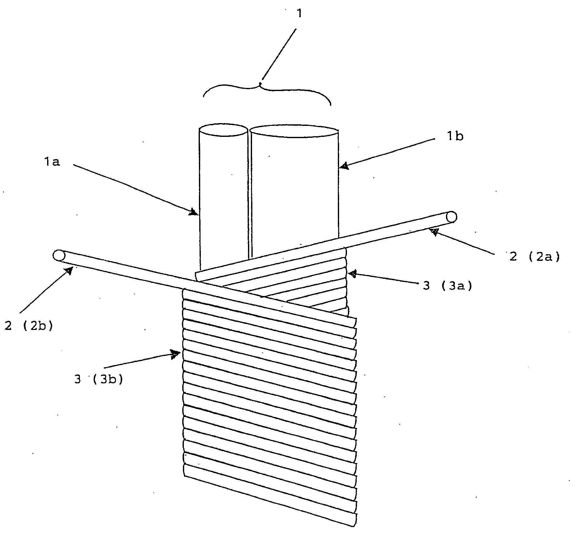
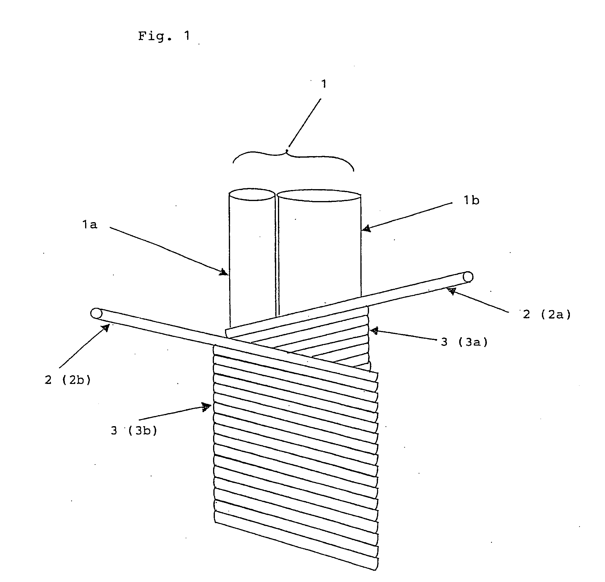
The present invention is a composite yarn that includes a metal thin wire and an attending yarn of a filament yarn wound around the metal thin wire at a specified turns. The composite yarn is then wrapped with a covering fiber to form a covering layer. The composite yarn can be used to produce a cut-resistant glove by knitting it and plating it with a specified fiber to improve its elastic property, moisture absorption, and workability when putting on the glove. The invention also includes a method for making the composite yarn and a cut-resistant glove made from it.

Problems solved by technology

However, although having cut resistance, the above-mentioned conventional composite yarns are inferior in moisture absorption property and also inferior in knitting processability, for example, since the stainless wire and the glass fiber are sometimes ruptured in the case of producing gloves by knitting the composite yarns and gloves produced by knitting the composite yarns give uncomfortable putting-on-feeling or use feeling, and particularly, the ruptured stainless wire and glass fiber irritatingly stimulate the skin, and therefore, the workability in the case where the gloves are put on is not satisfactory.
Especially, there is a serious problem that the stainless wire and glass fiber used as cores are exposed to the outside of the composite yarns and prickly irritate hands and fingers.

Method used


Image

  • Composite Yarn and Cut-Resistant Glove Using the Yarn
  • Composite Yarn and Cut-Resistant Glove Using the Yarn

Examples


example 1

[0071]One stainless thin wire with a thickness of 25 μm (SUS 304 stainless steel wire, manufactured by Nippon Seisen Co., Ltd.) and one ultra high molecular weight polyethylene filament yarn with 400 D / 390 F (trade name: Dyneema SK 60, manufactured by Toyobo Co., Ltd.) were united together by gently winding the ultra high molecular weight polyethylene filament yarn around the stainless thin wire at 33 turns / m and used as a core and one wooly-processed nylon fiber with 70 D / 24 F (a nylon yarn, manufactured by Hantex Co.) was wrapped at 634 turns / m around the core and further one wooly-processed nylon fiber with 70 D / 24 F (a nylon yarn, manufactured by Hantex Co.) was wrapped at 634 turns / m thereon in the opposite direction to form a covering layer and a composite yarn was obtained.

[0072]Next, using the obtained composite yarn, a glove was knitted by a 10 G knitting machine to obtain a sample glove.

[0073]The obtained sample glove had the cut resistance in the 5 CE level and was found ...

example 2

[0074]One stainless thin wire with a thickness of 25 μm (SUS 304 stainless steel wire, manufactured by Nippon Seisen Co., Ltd.) and one ultra high molecular weight polyethylene filament yarn with 400 D / 390 F (trade name: Dyneema SK60, manufactured by Toyobo Co., Ltd.) were united together by gently winding the ultra high molecular weight polyethylene filament yarn around the stainless thin wire at 10 turns / m and used as a core and one wooly-processed nylon fiber with 70 D / 24 F (a nylon yarn, manufactured by Hantex Co.) was wrapped at 634 turns / m around the core and further one wooly-processed nylon fiber with 70 D / 24 F (a nylon yarn, manufactured by Hantex Co.) was wrapped at 634 turns / m thereon in the opposite direction to form a covering layer and a composite yarn was obtained.

[0075]Next, using the obtained composite yarn, a glove was knitted by a 10 G knitting machine to obtain a sample glove.

[0076]The obtained sample glove had the cut resistance in the 5 CE level and was found h...

example 3

[0077]One stainless thin wire with a thickness of 25 μm (SUS 304 stainless steel wire, manufactured by Nippon Seisen Co., Ltd.) and one ultra high, molecular weight polyethylene filament yarn with 400 D / 390 F (trade name: Dyneema SK60, manufactured by Toyobo Co., Ltd.) were united together by gently winding the ultra high molecular weight polyethylene filament yarn around the stainless thin wire at 55 turns / m and used as a core and one wooly-processed nylon fiber with 70 D / 24 F (a nylon yarn, manufactured by Hantex Co.) was wrapped at 634 turns / m around the core and further one wooly-processed nylon fiber with 70 D / 24 F (a nylon yarn, manufactured by Hantex Co.) was wrapped at 634 turns / m thereon in the opposite direction to form a covering layer and a composite yarn was obtained.

[0078]Next, using the obtained composite yarn, a glove was knitted by a 10 G knitting machine to obtain a sample glove.

[0079]The obtained sample glove had the cut resistance in the 5 CE level and was found ...


PUM

PropertyMeasurementUnit
thicknessaaaaaaaaaa
thicknessaaaaaaaaaa
thicknessaaaaaaaaaa

Abstract

A composite yarn is provided which comprises a core and a covering layer formed by wrapping a covering fiber around the core, the core being composed of a metal thin wire and an attending yarn comprising a filament yarn, wherein the attending yarn is wound around the metal thin wire at 5 to 60 turns per meter of the metal thin wire. A cut-resistant glove formed of the composite yarn is also provided. The composite yarn of the present invention is preferably usable for protective products such as protective fabrics, protective clothes, protective aprons and protective gloves used for protecting workers and a cut-resistant glove formed of the composite fiber is excellent not only in moisture absorption property, but also in putting-on-feeling, use feeling and workability in the state of being put on.

Description

TECHNICAL FIELD[0001]The present invention relates to a composite yarn and a cut-resistant glove using the composite yarn and, more particularly, to a composite yarn to be used for protective products such as protective fabrics, protective clothes, protective aprons for cutting workers in edible meat processing works where sharp blades are used, glass producing or processing works or metal processing works where glass and metal plates with sharp edges are handled and a cut-resistant glove using the composite yarn.BACKGROUND ART[0002]As such types of yarns, use of metal yarn (wire) alone for armors or the like has formerly been a main stream especially in Europe. In recent years, to make such yarn lightweight and to improve the workability and strength, various kinds of composite yarns comprising metal yarn in combination with cotton yarn and high strength filaments have been proposed.[0003]For example, a core-sheath composite yarn produced by winding a synthetic fiber and thus cover...

Claims


Application Information

Patent Timeline
Patent Type & Authority Applications(United States)
IPC IPC(8): D02G3/36A41D19/00
CPCA41D19/01511D02G3/12D04B1/28D02G3/442D02G3/38
Inventor TAKADA, TERUYOSHI
Owner SHOWA GLOVE
Learn More