Composite Roll Bearing
a technology of rolling bearings and bearings, applied in the direction of roller bearings, mechanical equipment, rotary machine parts, etc., can solve the problems of large frictional force and inability to highly precise positioning, and achieve the effect of reducing the frictional resistance of rolling objects
- Summary
- Abstract
- Description
- Claims
- Application Information
AI Technical Summary
Benefits of technology
Problems solved by technology
Method used
Image
Examples
embodiment 1
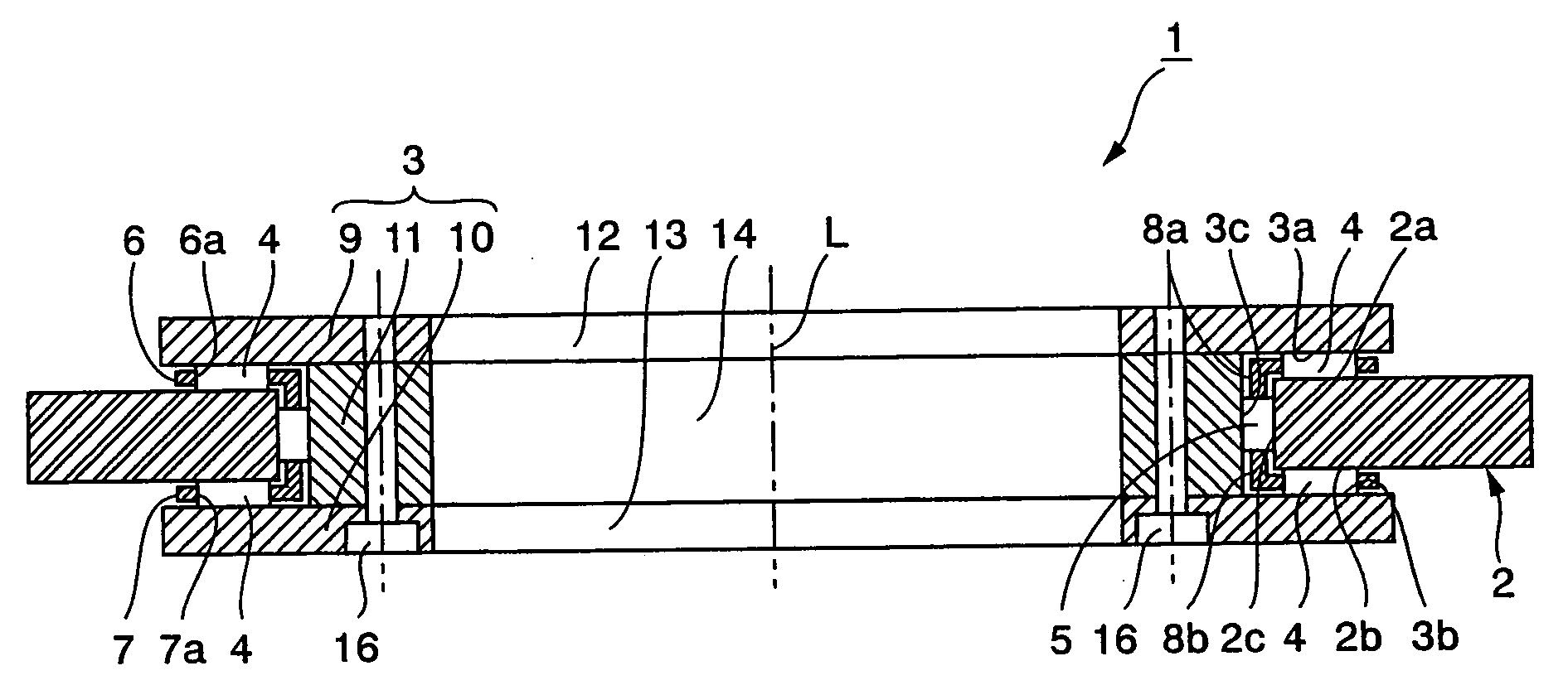
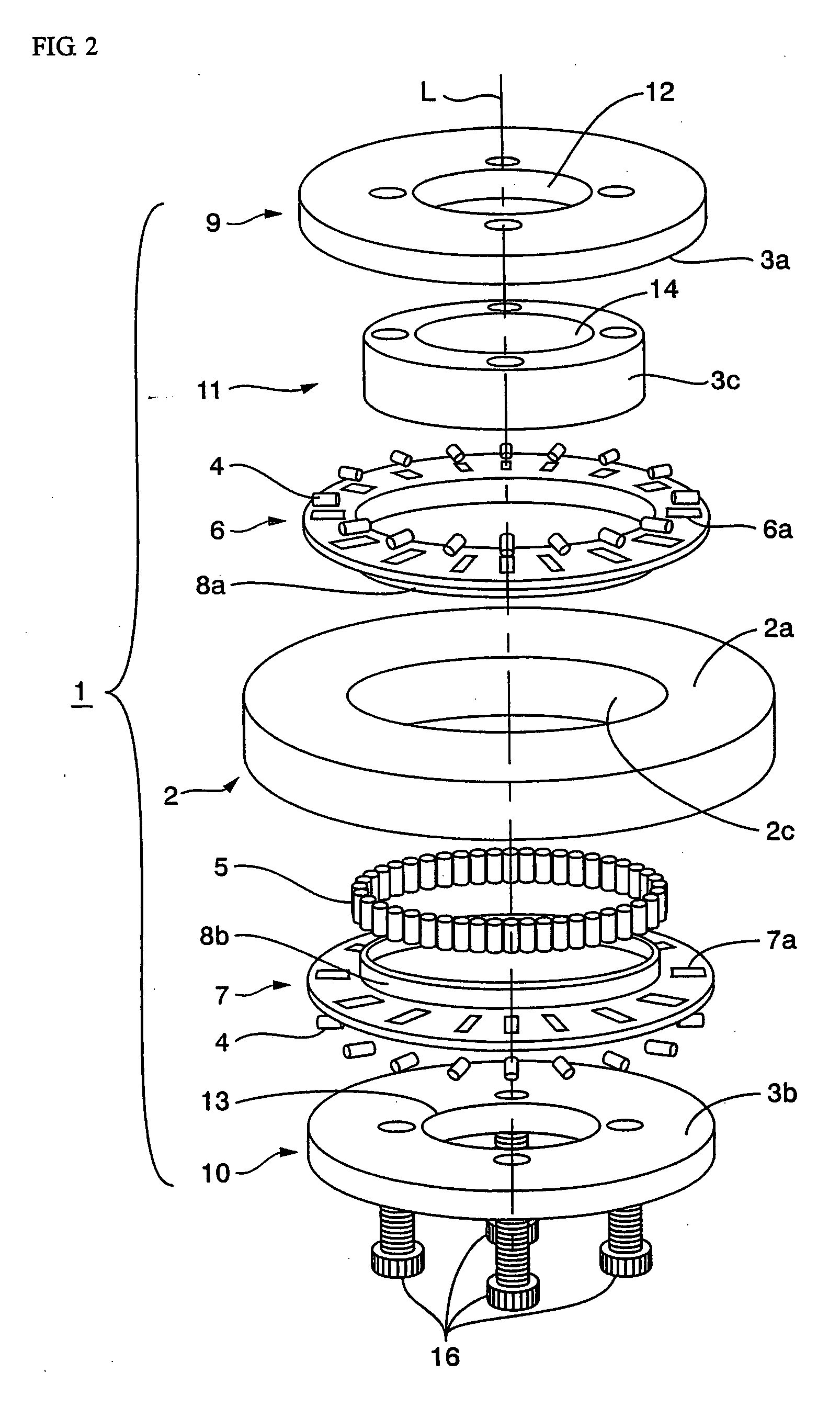
[0055]FIG. 1 is a cross-sectional view of a composite roll bearing according to the present invention, and FIG. 2 is an exploded perspective view thereof. As shown in these diagrams, a composite roll bearing 1 has an annular outer ring (first race ring) 2 comprising a circular inner peripheral surface 2c, and also comprising end-surface portions 2a, 2b linked to both ends of the circular inner peripheral surface 2c. The bearing also has an annular inner ring (second race ring) 3 in which a groove-shaped cross-sectional portion is formed and which comprises a first receiving surface 3a that faces the end-surface portion 2a at specified intervals, a second receiving surface 3b that faces the other end-surface portion 2b at specified intervals, and a third receiving surface 3c that faces the circular inner peripheral surface 2c at specified intervals.
[0056]FIG. 1 first annular race for thrust bearing is restricted by the end-surface portion 2a of the outer ring 2 and the first receivin...
embodiment 2
[0064]FIG. 4 is a cross-sectional view depicting another example of the composite roll bearing 1. The composite roll bearing 1A of the present example has an annular inner ring (first race ring) 3A, and an annular outer ring 2A (second race ring) having a groove-shaped cross section. The outer ring comprises first, second, and third receiving surfaces 2d, 2e, 2f that are placed opposite, and are separated by specified intervals from, outer peripheral side portions 3d, 3e at both end surfaces of the inner ring 3A, and from a circular outer peripheral surface 3f.
[0065]Thrust bearing rollers 4 capable of supporting thrust loads are located between one end-surface outer peripheral portion 3d of the inner ring 3A and the first receiving surface 2d of the outer ring 2A, and also between the other end-surface outer peripheral portion 3e of the inner ring 3A and the second receiving surface 2e of the outer ring 2A. Radial bearing rollers 5 capable of supporting radial loads are located bet...
PUM
 Abstract
Description
Claims
Application Information
 - R&D Engineer
- R&D Manager
- IP Professional
- Industry Leading Data Capabilities
- Powerful AI technology
- Patent DNA Extraction
Browse by: Latest US Patents, China's latest patents, Technical Efficacy Thesaurus, Application Domain, Technology Topic, Popular Technical Reports.
© 2024 PatSnap. All rights reserved.Legal|Privacy policy|Modern Slavery Act Transparency Statement|Sitemap|About US| Contact US: help@patsnap.com


