
Laser System for Hard Body Tissue Ablation

a laser system and hard body technology, applied in the field of laser systems, can solve the problems of material removal, undesirable heating of surrounding tissue, and reduce the effectiveness of lasers, and achieve the effect of improving efficiency

Inactive Publication Date: 2008-11-20
FOTONA D D
View PDF12 Cites 27 Cited by
  • Summary
  • Abstract
  • Description
  • Claims
  • Application Information

AI Technical Summary

Benefits of technology

[0005]As a compromise, in the dental operating methods according to the prior art, as known for example from US 2003 / 0158544 A1, individual pulses with a pulse length of approximately 25 μs (microseconds) to 150 μs and a pulse period of approximately 16 ms (milliseconds) are used. The above described disadvantageous effects of heating the surroundings and shielding are however overcome only to an unsatisfactorily degree. The efficiency and obtainable treatment speed are minimal.
[0006]The invention has the object to further develop a laser system of the aforementioned kind in such a way that its efficiency is improved.SUMMARY OF THE INVENTION
[0007]This object is solved by a laser system wherein the pumped laser has a inversion population remaining time, the inversion population remaining time being the time within which, in the absence of pumping, the remaining inversion population of the laser energy status is reduced by 90% and wherein the pulse spacing is in the range of ≧50 μs and ≦ to the inversion population remaining time.
[0008]A laser system for hard body tissue ablation is proposed, comprising a pumped laser, wherein the laser system is adapted to be operated in pulsed operation with several individual pulses of a temporally limited pulse length and wherein the individual pulses follow one another in a temporal pulse period, and are separated by temporal pulse spacing. Here, the temporal pulse spacing is defined as the temporal difference between the end of one single pulse and the beginning of the next single pulse. The pumped laser has an inversion population remaining time that is the time within which in the absence of pumping the remaining inversion population of the laser energy status is reduced by 90%, i.e. to 10% of the initial value. The pulse spacing is in the range of≧50 μs, in particular ≧80 μs, and less than the inversion population remaining time.
[0009]It is important to note that the inversion population remaining time is not always equal to the spontaneous decay time of the upper laser level. For example, in laser materials with high concentration of laser active atoms or ions (such as for example Er:YAG), or with appropriately chosen additional dopants (such as for example the Cr ions in Er:Cr:YSGG), the inversion population decay process, due to the energy up-conversion processes among interacting atoms or ions, may not be exponential, and subsequently the remaining time can be significantly longer than the spontaneous decay time. The inversion population time may in such cases vary with the inversion population and thus can be determined only approximately.
[0010]In a preferred further embodiment, the laser is an Er:YAG laser with an inversion population remaining time of ≦300 μs, wherein the temporal pulse spacing is ≦300 μs.

Problems solved by technology

The laser absorption leads to local heating with sudden water evaporation that, like a micro explosion, causes material removal.
At the same time, the pulsed operation contributes to heat being generated at the treatment location only for a very short time period and within a locally limited area.
However, not only the aforementioned sudden water evaporation is generated by means of the temporally limited pulse length of an individual pulse but also an undesirable heating of the surrounding tissue is caused.
Moreover, at the beginning of an individual pulse a small cloud of water vapor and ablated particles is produced that shields the treatment location with regard to the temporally following section of the individual pulse and therefore reduces its effectiveness.
However, such an operating scheme will reduce the efficiency in other ways.
Therefore, according to a generally accepted teaching among persons skilled in the art, short pulses of low energy and high repetition rate have a bad efficiency and therefore provide minimal processing speed.
The above described disadvantageous effects of heating the surroundings and shielding are however overcome only to an unsatisfactorily degree.
The efficiency and obtainable treatment speed are minimal.

Method used


Image

  • Laser System for Hard Body Tissue Ablation
  • Laser System for Hard Body Tissue Ablation
  • Laser System for Hard Body Tissue Ablation

Examples


Embodiment Construction

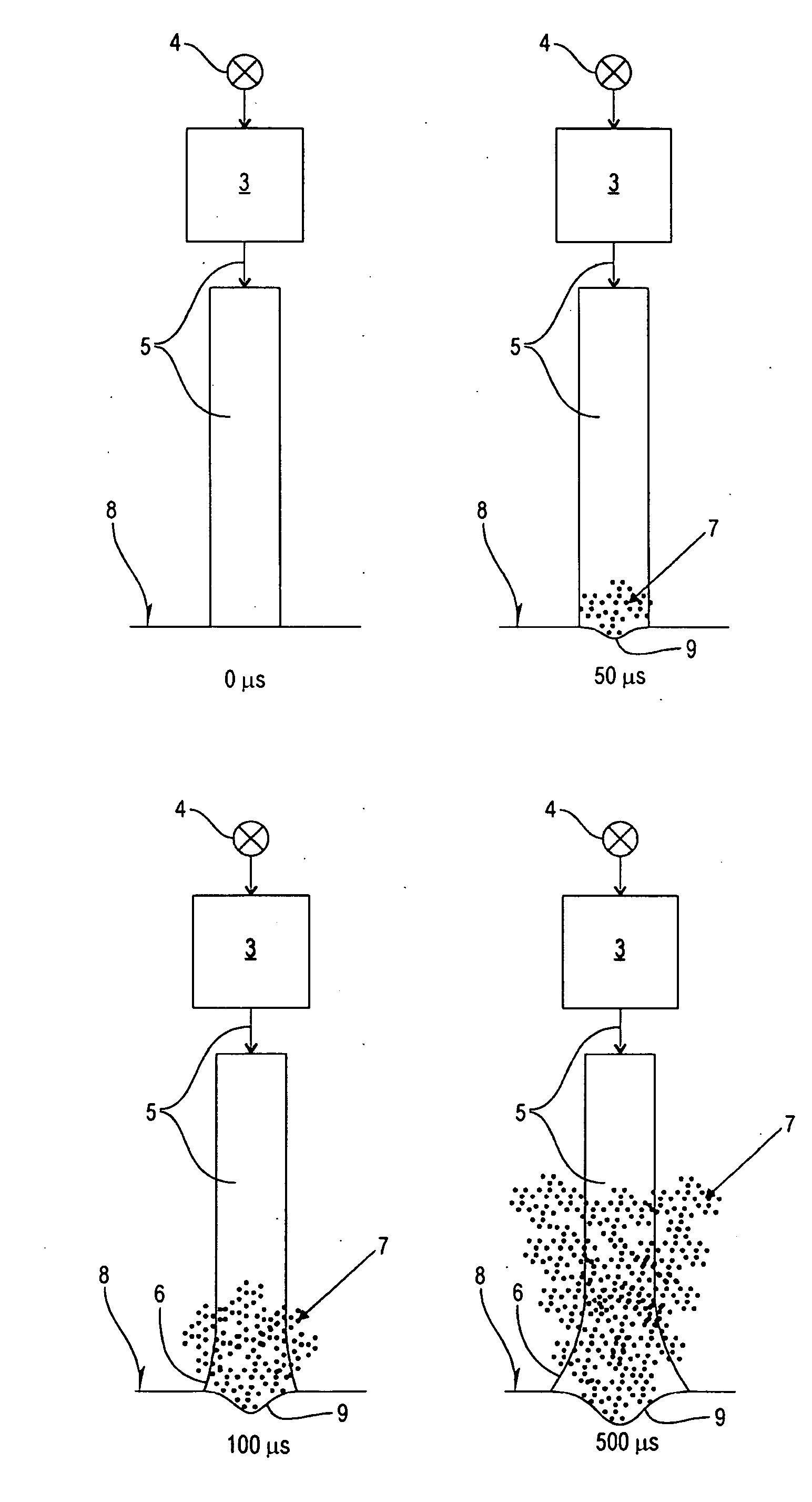
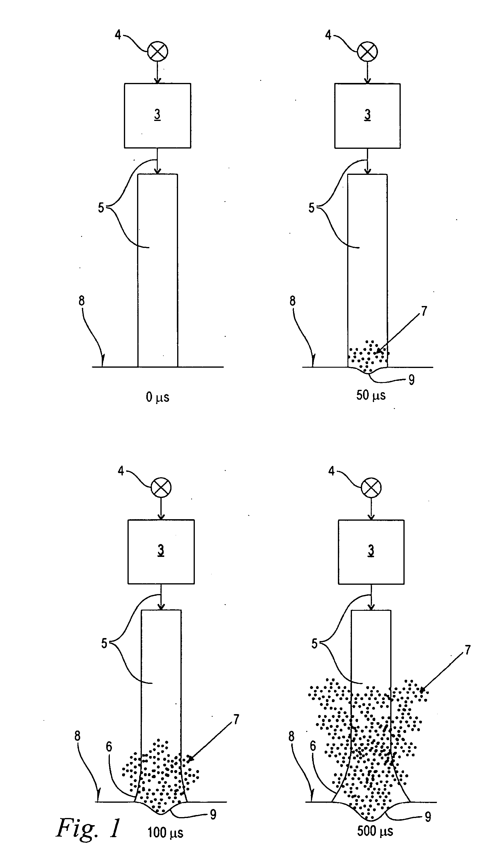
[0031]FIG. 1 shows a schematic illustration of a debris cloud 7 generated during the course of a single laser pulse at four different points of time, namely at the beginning of the single laser pulse at 0 μs, followed by subsequent time steps of 50 μs, 100 μs and 500 μs. A laser system comprises a laser 3 that is a solid state laser and is pumped by a flash lamp 4. The laser is a solid-state laser with an inversion population remaining time tR of ≦200 μs, as illustrated in FIGS. 6, 7. The inversion population remaining time tR is the time within which in the absence of pumping the remaining inversion population of the laser energy status is reduced by 90%. The laser is preferably an Er:YAG with an inversion population remaining time tR of ≦300 μs, or an Er:YSGG (or Er Cr:YSGG) laser with an inversion population remaining time tR of ≦3200 μs (FIG. 7). However, other solid state lasers or any other type of lasers such as liquid, diode, gas or fiber lasers can be used.

[0032]During pump...


PUM


Abstract

A laser system for hard body tissue ablation has a pumped laser, wherein the laser system is operated in pulsed operation with several individual pulses of a temporally limited pulse length and wherein the individual pulses follow one another with temporal pulse spacing. The pumped laser has an inversion population remaining time, the inversion population remaining time being the time within which, in the absence of pumping, the remaining inversion population of the laser energy status is reduced by 90%. The pulse spacing is in the range of ≧50 μs and ≦ to the inversion population remaining time.

Description

BACKGROUND OF THE INVENTION[0001]The invention relates to a laser system wherein the laser system is adapted to be operated in pulsed operation with several individual pulses of a temporally limited pulse length and wherein the individual pulses follow one another with temporal pulse spacing.[0002]In the field of dentistry or the like, lasers are used for removal of hard body tissues such as dental enamel, dentine or bone material. The material removal in hard tissue ablation is based on a pronounced absorption of the laser in water; despite the minimal water contents or presence of water in hard body tissue, this enables a satisfactory material removal. The laser absorption leads to local heating with sudden water evaporation that, like a micro explosion, causes material removal.[0003]The solid-state lasers that are typically used in the field of hard tissue ablation are operated in pulsed operation as a result of their system requirements in order to avoid overheating of the laser...

Claims


Application Information

Patent Timeline
Patent Type & Authority Applications(United States)
IPC IPC(8): H01S3/11H01S3/10A61N5/06
CPCA61B18/20A61B2017/00154A61C1/0046
Inventor MARINCEK, MARKOLUKAC, MATJAZ
Owner FOTONA D D
Learn More