Cutting Devices

Inactive Publication Date: 2008-11-20
STRAVITZ DAVID M
View PDF17 Cites 3 Cited by
  • Summary
  • Abstract
  • Description
  • Claims
  • Application Information

AI Technical Summary

Benefits of technology

[0010]It is still another object of some embodiments of the present invention to provide new and improved cutting devices which include multiple blades, each cutting blade being capable of having a different cutting edge or differently configured cutting construction to enable a plurality of different cuts to be made using a single device. This avoids the need to purchase and use multiple scissors or the need to make a blade change when using a rotary cutter in order to make different cuts.
[0011]It is yet another object of some embodiments of the present invention to provide new and improved cutting devices which substantially eliminate the risk of injury caused by exposed blades.
[0012]It is another object of some embodiments of the present invention to provide new and improved cutting devices which reduce the risk of injury caused by exposed blades yet enable long-lasting use of the cutting devices.
[0016]To prevent the user from being cut by one cutting blade when the other cutting blade is being used, yet still enable both cutting blades to be used when desired, a blade guard is movably connected to the cutting portion and movable between a first position in which it is alongside all of a first one of the cutting blades but not all of a second one of the cutting blades (in which case, the second one can be used by the user) and a second position in which it is alongside all of the second cutting blade but not all of the first cutting blade (in which case, the first one can be used by the user). The blade guard is arranged such that when it is alongside all of the cutting blade not in use, it extends up to or beyond a cutting edge of this cutting blade and therefore prevents a person from coming into contact with the cutting edge and being cut thereby.

Problems solved by technology

An issue which arises in the industries mentioned above is that it is often desired to make a decorative cut, i.e., a cut which is not the typical straight line made by standard scissors or an Exacto knife.
Another concern about cutting devices is the potential for harm when a person inadvertently brushes against an exposed blade while handling the cutting device or mishandles a cutting blade when replacing a blade.
For this reason, cutting devices with exposed blades and / or replaceable blades have not been highly welcomed by elderly people who have difficulty in handling the small blades and are reluctant to risk the potential for serious injury caused by the sharp blades.

Method used


Image

  • Cutting Devices
  • Cutting Devices
  • Cutting Devices

Examples


first embodiment

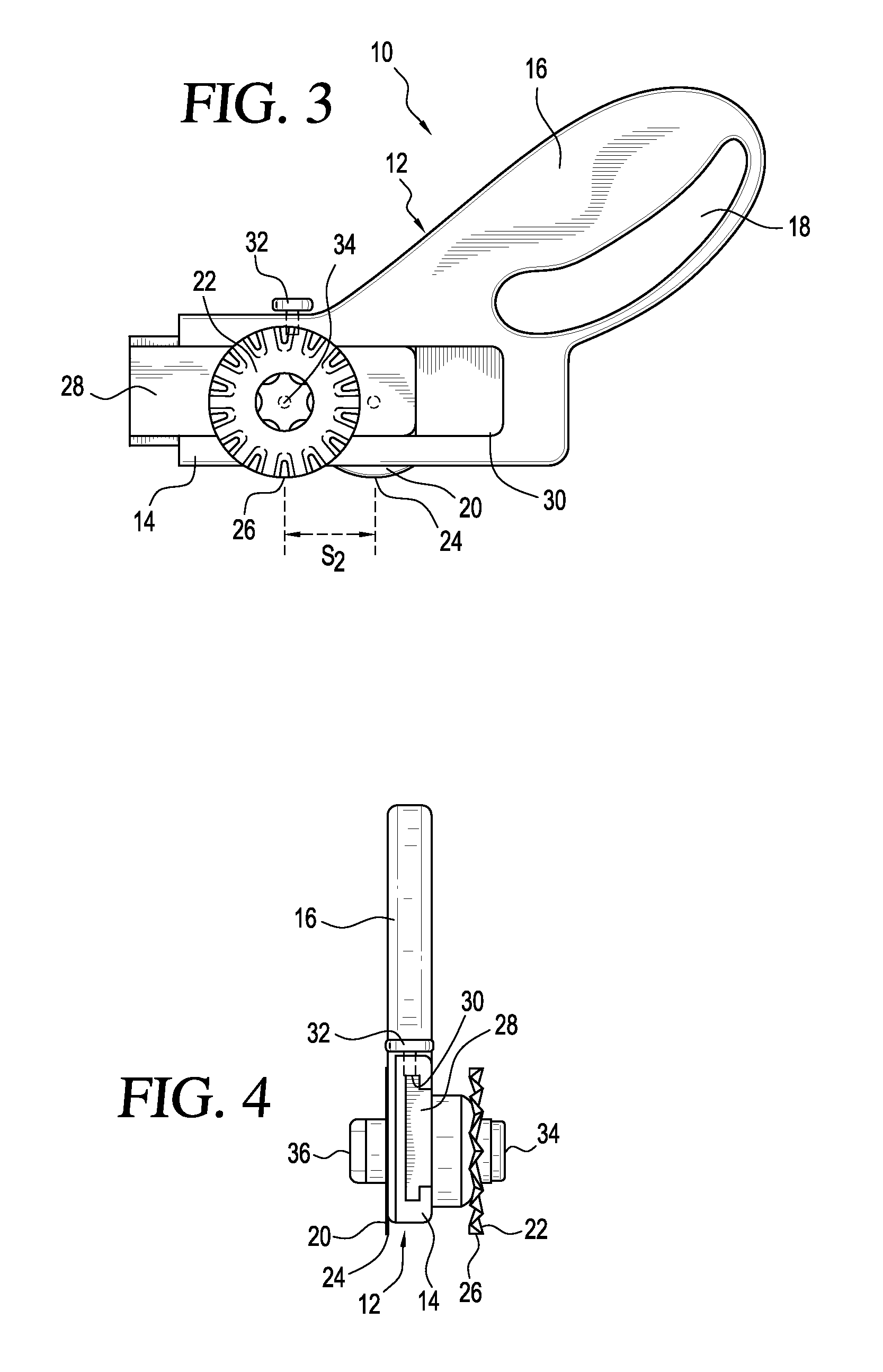
[0065]Referring to the accompanying drawings wherein like reference numbers refer to the same or similar elements, a cutting device 10 in accordance with the invention is shown in FIGS. 1-4 and generally provides for variable longitudinal spacing between two cutting blades, i.e., the position of one cutting blade in the longitudinal direction of the cutting device is adjustable relative to the position of the other cutting blade.

[0066]Cutting device 10 includes an elongate body 12 having a blade-mounting portion 14 and a handle portion 16 extending from the blade-mounting portion 14. Handle portion 16 includes a finger-receiving aperture 18 into which one or more fingers of the user are placed to enable the user to grip the handle portion 16 and effectively use the cutting device 10. Handle portion 16 may be contoured to fit within the palm of the user's hand.

[0067]A pair of substantially parallel cutting blades 20, 22 are rotatably mounted on opposite sides of the blade-mounting po...

second embodiment

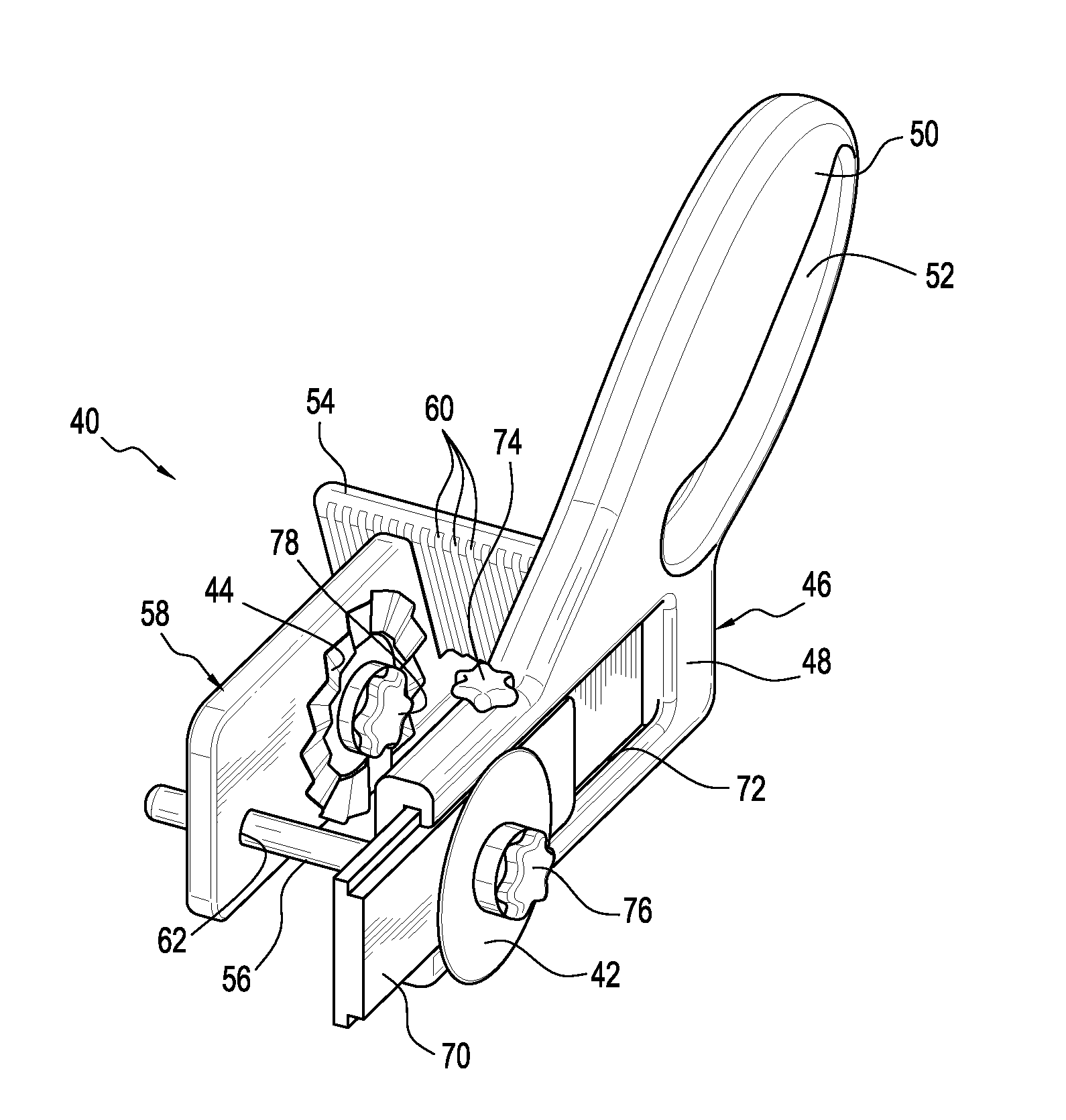
[0076]a cutting device 40 in accordance with the invention is shown in FIGS. 5-10 and generally provides for both variable longitudinal spacing between two cutting blades and variable transverse spacing the two cutting blades, i.e., the position of one cutting blade in a transverse direction of the cutting device is adjustable relative to the position of the other cutting blade. Variable transverse spacing involves the ability to adjust the cutting width defined as the transverse distance between the planes in which the cutting blades 42, 44 rotate. Cutting device 40 thereby enables the formation of strips of material having different widths. The form, orientation and shape of the cutting blades 42, 44 may be as described above with reference to cutting blades 20, 22.

[0077]Cutting device 40 includes an elongate body 46 having a blade-mounting portion 48 and a handle portion 50 extending from the blade-mounting portion 48. Handle portion 50 includes a finger-receiving aperture 52 int...

third embodiment

[0089]FIGS. 11-14 show a cutting device 82 in accordance with the invention which is similar to the one shown in FIGS. 5-10 except that longitudinal slot 72 is extended across the entire body 46, i.e., from one longitudinal end to the opposite longitudinal end, and an additional sliding member 84 is arranged in slot 72. A third cutting blade 86 is mounted on sliding member 84 via locking knob 88 and may be in substantially the same rotation plane as cutting blade 42 and thus also parallel to cutting blade 44. Alternatively, cutting blade 86 may be arranged in a rotation plane which intersects the rotation planes of cutting blade 42 and / or cutting blade 44.

[0090]Sliding members 70, 84 can be fixed in slot 72 by locking screws 90 arranged on the sliding members 70, 84 and passing therethrough into frictional contact with the body 46 when the sliding members 70, 84 are fixed in position. Contact between the locking screws 90 and the body 46 prevents movement of the sliding members 70, ...


PUM


Abstract

Hand-held cutting devices including a body having a handle portion and a cutting portion, and one or more rotatable cutting blades arranged on the cutting portion. The cutting portion is movable into different positions relative to the handle portion, or vice versa. When two cutting blades are provided, they may be arranged on opposite sides of a mounting wall and axially offset from one another. To prevent the user from being cut by one cutting blade when the other cutting blade is being used, yet still enable both cutting blades to be used when desired, a blade guard is movably connected to the cutting portion and movable between two positions in which it is alongside all of one cutting blade (the one not being used) but not all of the other cutting blade (the one being used), and vice versa.

Description

CROSS REFERENCE TO RELATED APPLICATIONS[0001]This application is a continuation-in-part of U.S. patent application Ser. No. 11 / 251,642 filed Oct. 14, 2005 which claims priority under 35 U.S.C. §119(e) of U.S. provisional patent application Ser. No. 60 / 619,248 filed Oct. 15, 2004 and U.S. provisional patent application Ser. No. 60 / 689,338 filed Jun. 10, 2005, all of which are incorporated by reference herein.FIELD OF THE INVENTION[0002]The present invention relates generally to cutting devices for cutting sheet material.BACKGROUND OF THE INVENTION[0003]Hand-held cutting devices are used in various industries and hobbies such as quilting, sewing and scrap booking, and are also often used by graphic artists, architects, model makers and the like. Basic types of hand-held cutting device include scissors, rotary cutters and Exacto knives which are typically used to make single cuts in sheet material or other substrates.[0004]Rotary cutters typically have a hand-held body, a circular blad...

Claims


Application Information

Patent Timeline
IPC IPC(8): B26B13/00B26B27/00B26B29/00
CPCB26B29/02B26B25/005
Inventor STRAVITZ, DAVID M.
Owner STRAVITZ DAVID M
Why Eureka
Try Eureka