Zig-zag array resonators for relatively high-power hts applications

a zig-zag array and hts technology, applied in the field of microwave filters, can solve the problems of affecting the size and cost of the resonator for a given, corresponding compromise in filter steepness or selectivity, and conductors with inherent lossiness

Inactive Publication Date: 2008-11-13
SUPERCONDUCTOR TECHNOLOGIES INC
View PDF9 Cites 9 Cited by
  • Summary
  • Abstract
  • Description
  • Claims
  • Application Information

AI Technical Summary

Benefits of technology

[0014]The basic resonator structures may be, e.g., planar structures, such as microstrip structures, and may be composed of a suitable material, such as a high temperature superconductor (HTS) material. Each of the basic resonator structures may have a suitable nominal length, such as a half wavelength at the resonant frequency. Each of the basic structures may be, e.g., a zig-zag structure. The single resonator may have a suitable unloaded Q, such an unloaded Q that is at least 100,000. The filter may optionally comprise at least one electrically conductive element coupled between at least two of the basic resonator structures.

Problems solved by technology

In particular, such electrical filters are used to select desired electrical signal frequencies from an input signal by passing the desired signal frequencies, while blocking or attenuating other undesirable electrical signal frequencies.
In most filter technologies, achieving a low insertion loss requires a corresponding compromise in filter steepness or selectivity.
This requirement for low resistance tends to drive the size and cost of the resonators for a given technology.
These conductors have inherent lossiness, and as a result, the circuits formed from them have varying degrees of loss.
For resonant circuits, the loss is particularly critical.
The filters required are often quite complex with perhaps twelve or more resonators along with some cross couplings.
Yet the available size of usable substrates is generally limited.
In the case of narrow-band microstrip filters (e.g., bandwidths of the order of 2 percent, but more especially 1 percent or less), this size problem can become quite severe.
Though microwave structures using HTS materials are very attractive from the standpoint that they may result in relatively small filter structures having extremely low losses, they have the drawback that, once the current density reaches a certain limit, the HTS material saturates and begins to lose its low-loss properties and will introduce non-linearities.
Unfortunately, the lowest-frequency modes tend to have strong edge current densities, which will reduce power handling and unloaded Q values, and they are also very radiative.
This causes them to interact with the resonator housing (usually composed of normal metal), which will further reduce power handling and unloaded Q values.
Of course, the presence of numerous, nearby resonances in the filter response is a serious problem for many practical applications where solid adjacent stop bands are required.
Thus, power handling in HTS resonators is severely limited by current density saturation.

Method used


Image

  • Zig-zag array resonators for relatively high-power hts applications
  • Zig-zag array resonators for relatively high-power hts applications
  • Zig-zag array resonators for relatively high-power hts applications

Examples


Embodiment Construction

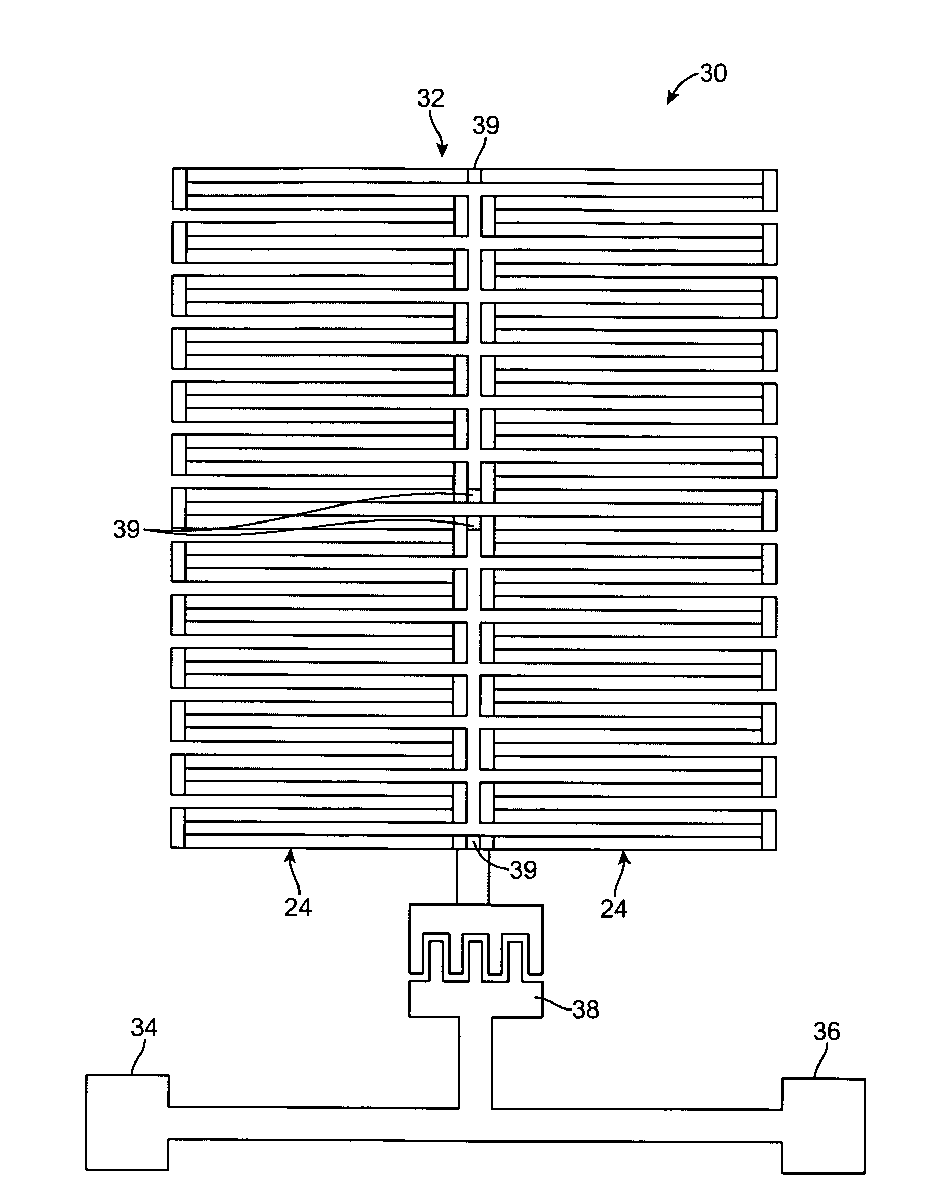
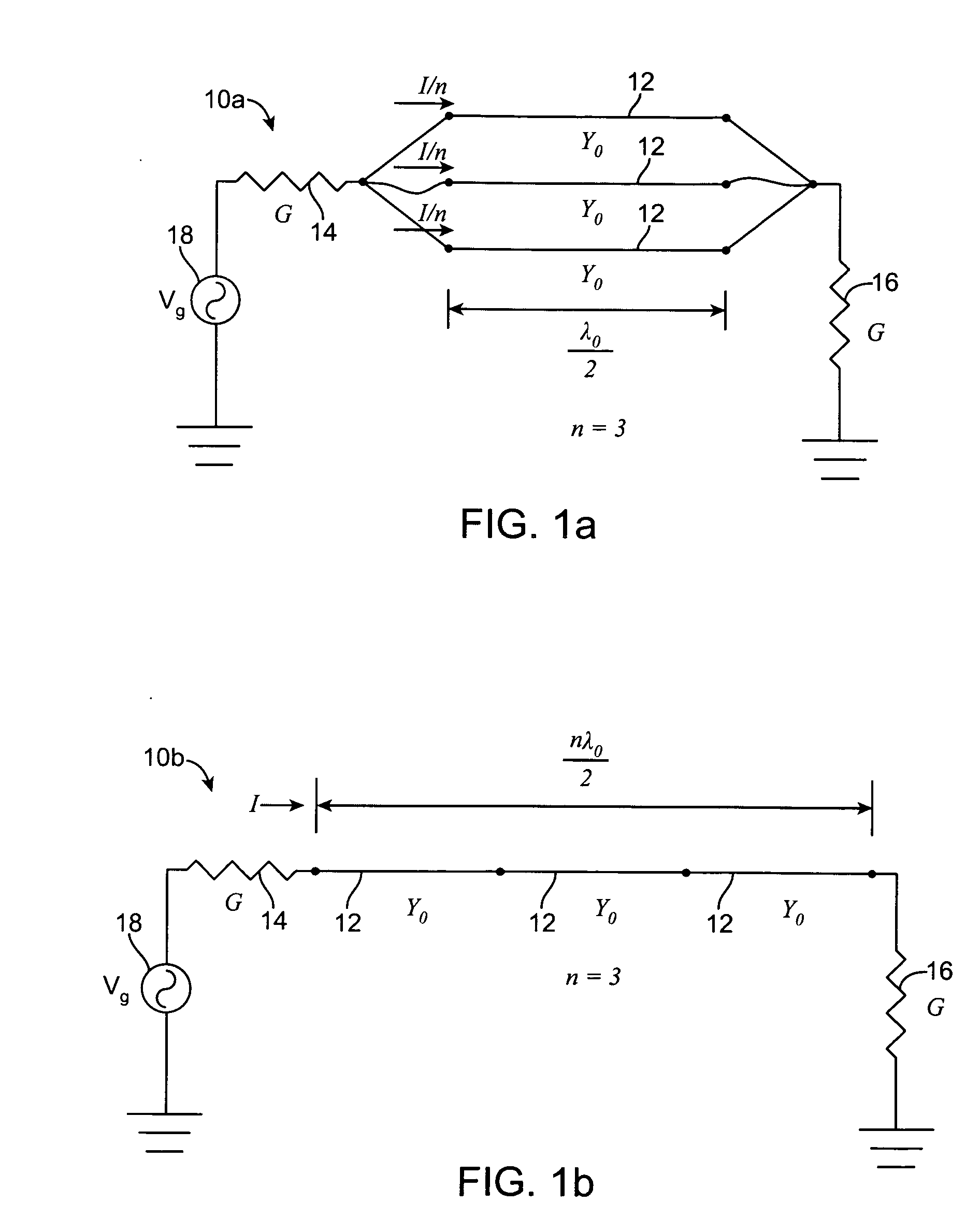
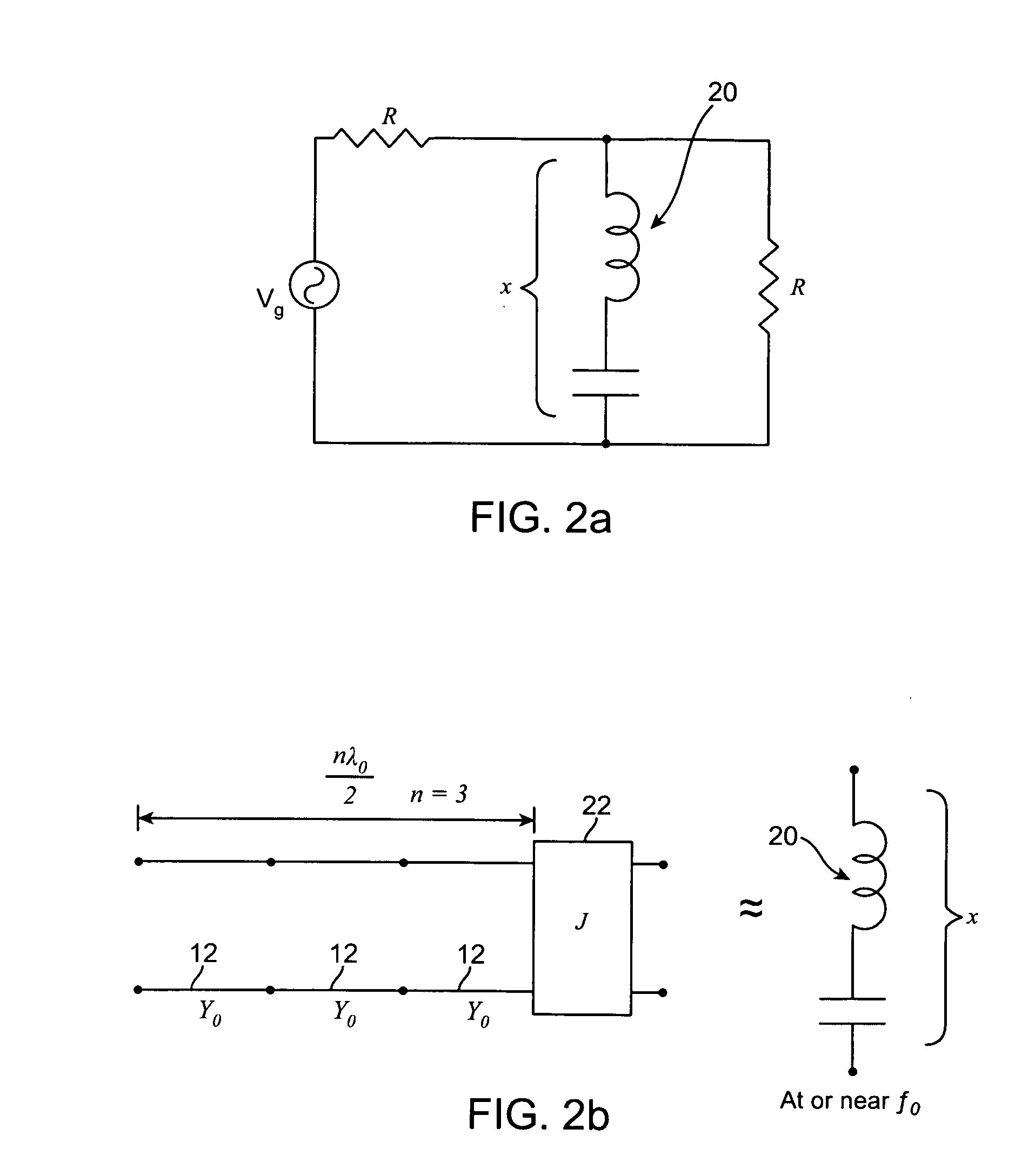
[0041]Each of the following described embodiments of filters comprises an array “basic resonators” that are connected together to create an overall resonant structure, so that the stored energy within the resonant structure is spread throughout the array of basic resonators, and the current density in any of the individual basic resonators will not be very large. As a result, the maximum current density within the resonant structure is minimized, so that the overall resonant structure has considerably higher power-handling ability than that of a basic resonator alone.

[0042]While the immediate focus herein is a relatively high-power HTS application, thereby increasing the importance of minimizing the maximum current density in the resonate structure, many of the same principles described herein would apply if the objective was to minimize the maximum electric field strength in the resonant structure. In either case, the principle is to spread the stored energy through the overall res...


PUM


Abstract

A narrowband filter comprises an input terminal, an output terminal, and an array of basic resonator structures coupled between the terminals to form a single resonator having a resonant frequency. The resonator array may be arranged in a plurality of columns of basic resonator structures, with each column of basic resonator structures having at least two basic resonator structures. The basic resonator structures in each column may be coupled between the terminals in parallel or in cascade. Two or more resonator arrays may be coupled to generate multi-resonator filter functions.

Description

RELATED APPLICATION[0001]This application claims priority from U.S. Provisional Patent Application Ser. No. 60 / 928,530, filed May 10, 2007, which is expressly incorporated herein by reference.FIELD OF THE INVENTION[0002]The present inventions generally relate to microwave filters, and more particularly, to microwave filters designed for narrow-band applications.BACKGROUND OF THE INVENTION[0003]Electrical filters have long been used in the processing of electrical signals. In particular, such electrical filters are used to select desired electrical signal frequencies from an input signal by passing the desired signal frequencies, while blocking or attenuating other undesirable electrical signal frequencies. Filters may be classified in some general categories that include low-pass filters, high-pass filters, band-pass filters, and band-stop filters, indicative of the type of frequencies that are selectively passed by the filter. Further, filters can be classified by type, such as But...

Claims


Application Information

Patent Timeline
Patent Type & Authority Applications(United States)
IPC IPC(8): H03H7/01
CPCH01P1/20354H01P1/203H01P7/08
Inventor MATTHAEI, GEORGE L.WILLEMSEN, BALAM A.PROPHET, ERIC M.TSUZUKI, GENICHI
Owner SUPERCONDUCTOR TECHNOLOGIES INC
Why Eureka
Try Eureka