Positioning method for kiln head burner in novel dry cement production line

A kiln head burner and dry-process cement technology, applied in the field of building materials, can solve the problems of unsmooth flame, incomplete combustion, rapid burning, etc., and achieve the increase of effective combustion space, reasonable heat distribution, and sufficient pulverized coal combustion space. Effect

Inactive Publication Date: 2019-04-16
GEZHOUBA SONGZI CEMENT
View PDF4 Cites 0 Cited by
  • Summary
  • Abstract
  • Description
  • Claims
  • Application Information

AI Technical Summary

Problems solved by technology

[0003] In order to solve the deficiencies of the existing technology, the present invention relates to a positioning method for the kiln head burner of a new type of dry process cement production line. , a new dry process cement production line kiln head burner positioning method is proposed

Method used


Image

  • Positioning method for kiln head burner in novel dry cement production line
  • Positioning method for kiln head burner in novel dry cement production line
  • Positioning method for kiln head burner in novel dry cement production line

Examples


Embodiment

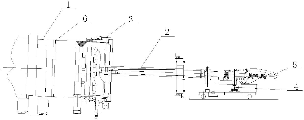
[0035] Such as figure 1 Among them, the coordinate position of the burner 2 center on the kiln hood is its basic position. Before determining the relative position of the burner 2 and the rotary kiln 1, the coordinate position of the end face of the burner 2 at the kiln mouth 3 should be determined first. First, measure the distance from the center of the support point of the burner 2 to the two ends of the rotary kiln 1 cylinder through the measuring device, and adjust the support point so that it is located on the central axis of the kiln cylinder. Then adjust the left and right position of the center point of the end face of the burner head relative to the center point of the kiln mouth, and adjust the left and right swinging handwheel of the burner so that the two center points are on the same vertical line. Then use a laser pointer to confirm with the center position of the oil pipe channel at the tail of the kiln head burner, adjust the elevation angle of the burner 2, a...


PUM


Abstract

The invention relates to a positioning method for a kiln head burner in a novel dry cement production line. The positioning method specifically comprises the following steps that S1, the center position of a supporting point of the burner is determined; S2, the center point position of the end face of the burner head is determined; and S3, the center position of a tail oil pipe channel of the kilnhead burner is determined. By adopting the positioning method, the length, the temperature and thermal distribution of a burning belt of a rotary kiln can be more suitable, the thickness of a kiln coating is moderate, coal ash sedimentation is more uniform, the yield of clinker can be effectively increased, the quality of the clinker can be effectively improved, and the service life of a kiln liner can be effectively prolonged.

Description

technical field [0001] The invention relates to a positioning method for a kiln head burner of a novel dry-process cement production line, which belongs to the technical field of building materials. Background technique [0002] The kiln head burner is one of the core equipment of the new dry process cement production process. The pulverized coal is measured by the pulverized coal scale, and the compressed air generated by the Roots blower is transported to the kiln head along the coal pipeline, and the compressed air generated by the primary fan is sprayed out through the burner and burned in the rotary kiln. The calcining of clinker in the rotary kiln provides heat; the burnt coal ash settles on the surface of the material and participates in the reaction. The relative position of the burner and the rotary kiln shell directly affects the flame shape, temperature field and flow field distribution in the rotary kiln, thereby affecting the quality of fired clinker and the se...

Claims


Application Information

Patent Timeline
Patent Type & Authority Applications(China)
IPC IPC(8): F27B7/34
Inventor 郑志龙黄凯何维朱精瑞向丛阳
Owner GEZHOUBA SONGZI CEMENT
Why Eureka
Try Eureka