
Machine tool

a technology of machine tools and workpieces, applied in the field of machine tools, can solve the problems of inability to acquire such precision, difficulty in machining short workpieces, and ineffective utilization of workpieces, and achieve the effects of effective utilization of workpieces, high rigidity and accuracy, and smooth guidan

Active Publication Date: 2008-11-13
STAR MICRONICS
View PDF9 Cites 5 Cited by
  • Summary
  • Abstract
  • Description
  • Claims
  • Application Information

AI Technical Summary

Benefits of technology

The present invention provides a machine tool that can smoothly guide and move a headstock along an axial direction of a main spindle with high rigidity and accuracy. The headstock is supported by a bed by way of a sliding bearing so as to be movable along an axial direction of the main spindle at a leading-edge portion close to a position for machining a workpiece. At a base-end portion spaced apart from the position for machining a workpiece, the headstock is smoothly guided and moved by way of a rolling bearing. This allows the main spindle to be guided by means of guide surfaces of simple shapes, and an attempt is made to enhance the machining precision and efficiency of a workpiece. The machine tool can guide and move a headstock, at a leading-edge portion close to a position for machining a workpiece, with high accuracy along an axial direction of a main spindle by means of a sliding bearing. The headstock is smoothly guided and moved by means of a rolling bearing. This allows the machine tool to effectively utilize a short workpiece, and enhance the accuracy and efficiency of machining of the workpiece.

Problems solved by technology

First, in the related-art configuration described in JP-UM-B-3-40488, in a state where the guide bush is attached forward of the main spindle, space including the length of the guide bush is formed between the main spindle and the guide bush, and a remaining material of a workpiece whose length corresponds to the space arises. Therefore, when the guide bush is in an attached state, the workpiece cannot be utilized effectively. In addition, in the case of a short workpiece, the guide bush interferes with the workpiece, thereby posing difficulty in machining the short workpiece.
In reality, acquisition of such precision is impossible.
Even if such precision can be achieved, very high cost will be incurred.
Therefore, if an attempt is made to actually provide the configuration described in JP-UM-B-3-40488, there is no alternative way but to weaken the rigidity of the guide to such an extent that the load imposed during machining cannot be born by the leading-edge side of the main spindle.
Therefore, difficulty is encountered in imparting high support rigidity to the main spindle during machining, which in turn reduces machining precision.
Therefore, the configuration of the guide surfaces is complicate.
Further, since the number of guide surfaces is large, there is a potential risk of a warp, and machining guide surfaces involves consumption of much effort, as well.

Method used


Image

  • Machine tool
  • Machine tool
  • Machine tool

Examples


first embodiment

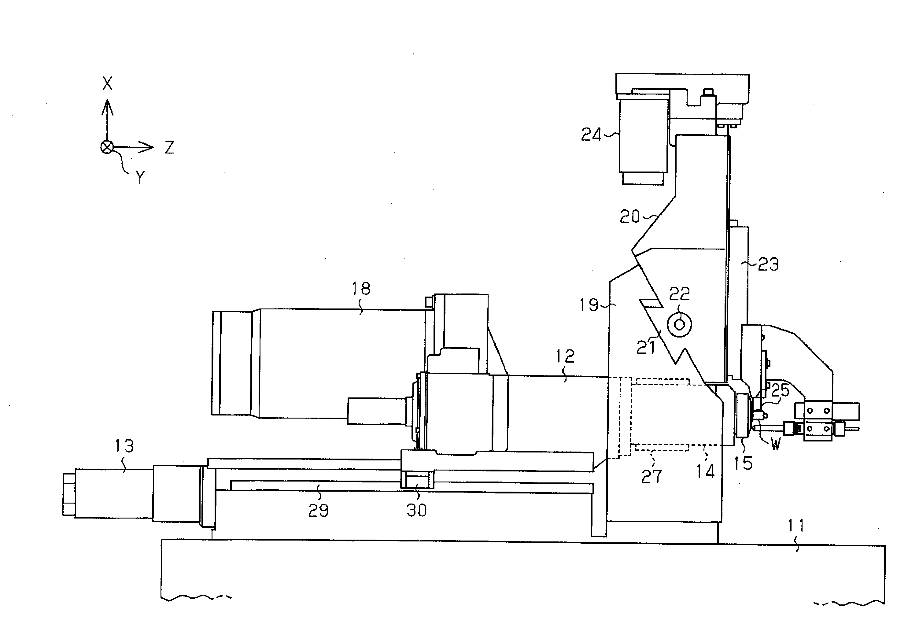
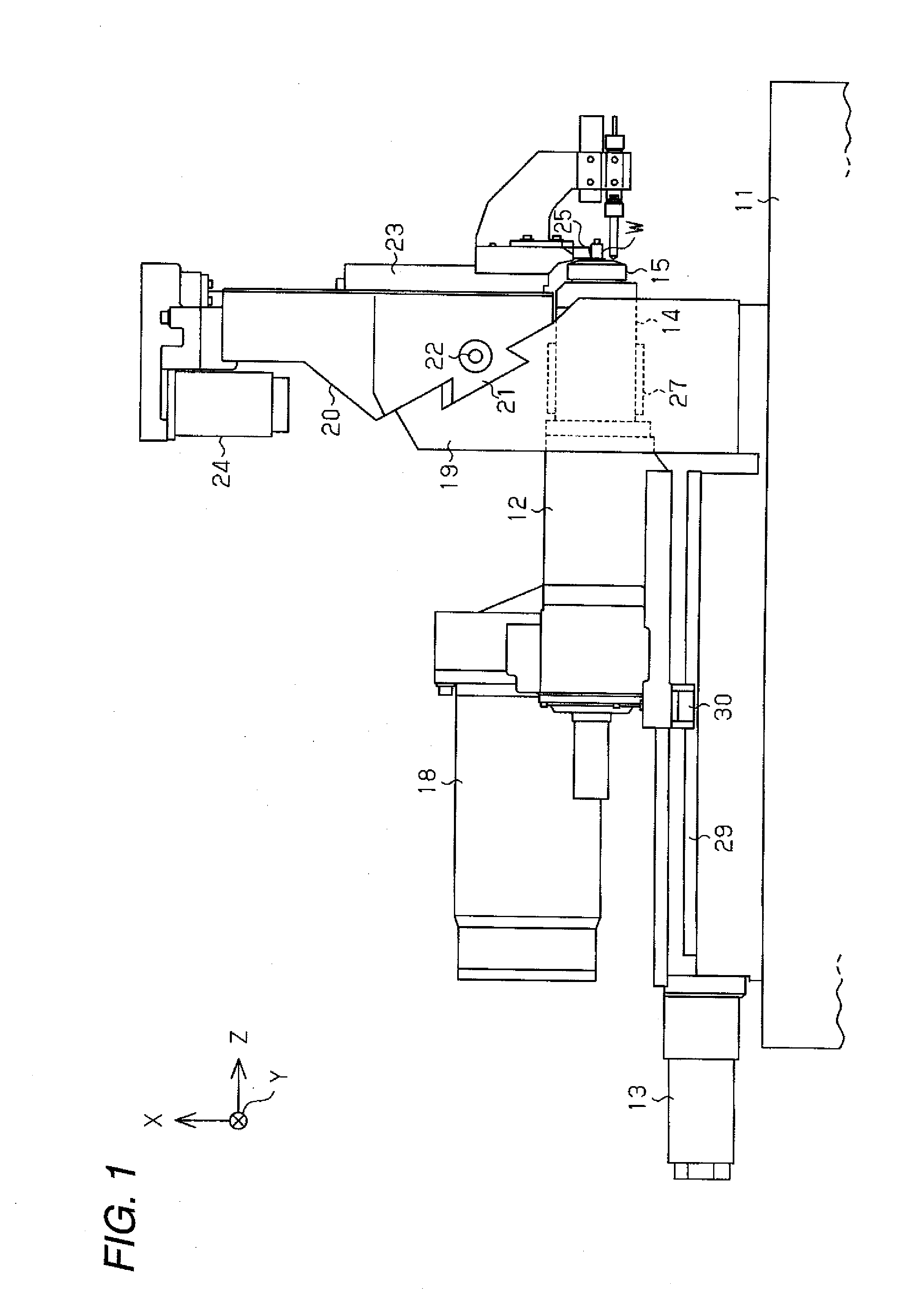
[0033]A first embodiment in which the present invention is embodied as a lathe of main spindle movable type will be described hereunder by reference to FIGS. 1 through 6.

[0034]As shown in FIGS. 1 and 2, in the lathe of main spindle movable type of the first embodiment, a headstock 12 is supported on a bed 11. A Z-axis movement motor 13 is disposed on the bed 11, and the headstock 12 is reciprocally actuated, at a base-end portion and a leading-edge portion thereof, by means of rotation of the motor 13 in a direction of a Z axis by way of an unillustrated ball screw feed mechanism.

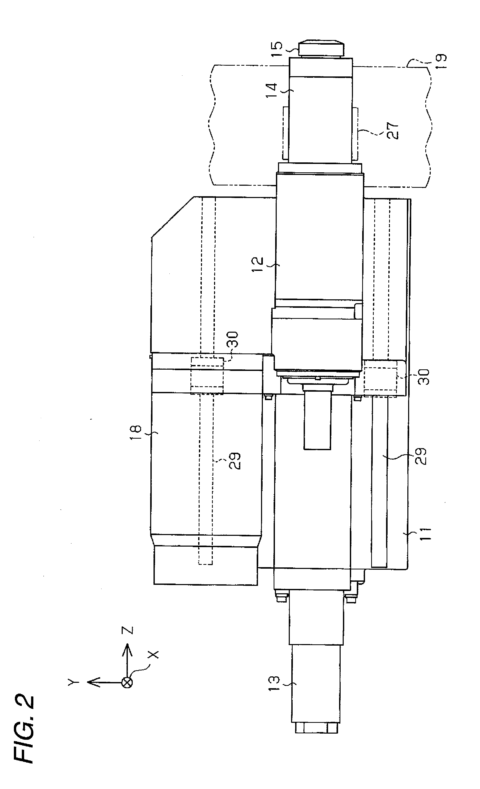
[0035]As shown in FIGS. 1 through 3, a cylindrical spindle sleeve 14 constituting a leading-edge portion of the headstock 12 is fixed to a front portion of the headstock 12. In the spindle sleeve 14, a main spindle 15 is supported so as to be rotatable around an axis extending in the direction of the Z axis by way of a plurality of bearings 16. A collet 17 for removably gripping a rod-shaped workpiece W is ...

second embodiment

[0050]As shown in FIGS. 7 and 8, in the second embodiment, a turret tool post 40 having a turret 40a is supported on the tool post support 19 along a pair of guide rails 41 so as to be movable in the direction of the X axis, and a plurality of tools 25 are supported by the turret tool post 40. The turret tool post 40 is reciprocally actuated in the direction of the X axis by way of a ball screw feed mechanism by means of an unillustrated X-axis movement motor, and the predetermined tools 25 are disposed at positions corresponding to machining positions on the workpiece W.

[0051]In the second embodiment, through holes are not formed in the tool post support 19, and a bearing element 42 is attached to an exterior surface of the tool post support 19. The cylindrical sliding bearing 27 analogous to that described in connection with the first embodiment is housed in the bearing element 42, and the leading-edge portion of the headstock 12 is inserted into and supported by the sliding beari...


PUM

PropertyMeasurementUnit
shapeaaaaaaaaaa
lengthaaaaaaaaaa
rigidityaaaaaaaaaa

Abstract

According to one embodiment, a machine tool for machining a workpiece includes: a main spindle that holds the workpiece to rotate the workpiece around a axis; a tool that is configured to machine the workpiece by working together with the main spindle; a headstock that rotatably supports the main spindle and includes a leading-edge portion and a base-end portion; and a bed that supports the headstock by a sliding bearing at the leading-edge portion and rolling bearings at two points of the base-end portion so that the headstock is movable along an axial line of the main spindle, wherein the two points of the base-end portion are spaced apart from each other in a direction orthogonal to the axial line of the main spindle.

Description

BACKGROUND OF THE INVENTION[0001]1. Field of the Invention[0002]The present invention relates to a machine tool that grips a rod-shaped workpiece at a leading edge of a main spindle and that subjects the workpiece to machining, such as cutting or boring, and more particularly to a machine tool made up of a lathe of main spindle movable type that moves a main spindle along an axis during machining.[0003]2. Background Art[0004]In relation to a machine tool of this type, a configuration as described in; for example, JP-UM-B-3-40488, has hitherto been proposed as a lathe of main spindle movable type that subjects an elongated rod-shaped workpiece to machining.[0005]In the related-art configuration described in JP-UM-B-3-40488, a guide bush for supporting forward of the main spindle the leading edge of the workpiece in an insertable manner can be removably attached. When the guide bush is in an attached state, the workpiece gripped by the main spindle is also supported by the guide bush ...

Claims


Application Information

Patent Timeline
Patent Type & Authority Applications(United States)
IPC IPC(8): B23B3/00
CPCB23B7/06Y10T82/25Y10T82/2562Y10T82/2552B23B2260/008
Inventor OZAWA, SATORU
Owner STAR MICRONICS
Learn More