Exhaust emission purifying apparatus for engine

Inactive Publication Date: 2008-11-13
NISSAN DIESEL MOTOR CO
View PDF1 Cites 24 Cited by
  • Summary
  • Abstract
  • Description
  • Claims
  • Application Information

AI Technical Summary

Benefits of technology

[0010]According to the exhaust emission purifying apparatus of the present invention, it is determined that the reducing agent supply system arranged on the downstream of the pump brings about clogging, when the reduction in the pressure of the liquid reducing agent remaining in the downstream of the pump and also in the upstream of the flow control valve by an amount equal to or more than a first predetermined pressure does not occur until the cumulative injection amount which is obtained by sequentially integrating the liquid reducing agent injection amount computed in real time based on the engine operating conditions reaches the predetermined amount after the pump for performing suction and supply of the liquid reducing agent out of the reducing agent tank is temporarily stopped. Namely, in a normal exhaust emission purifying process, in order to enable the injection amount of the liquid reducing agent to be controlled via the flow control valve, the pump is appropriately controlled according to the engine operating conditions, and the pressure of the liquid reducing agent in the downstream of the pump is held approximately constant. Then, if the pump is temporarily stopped, only the liquid reducing agent remaining in the downstream of the pump and also in the upstream of the flow control valve contributes to the injection-supply thereof. At this time, if the reducing agent supply system does not bring about clogging, the pressure of the liquid reducing agent is regularly reduced as the cumulative injection amount is increased. On the other hand, if the reducing agent supply system brings about clogging, since the liquid reducing agent practically injection-supplied by the injection nozzle is very few or nil, the reduction in the pressure of the liquid reducing agent is extremely small during the increase in the cumulative injection amount. Therefore, even if the injection-supply of the liquid reducing agent is temporarily stopped or dynamically changed according to the engine operating conditions, it is possible to determine with high accuracy whether or not clogging is brought about in the reducing agent supply system, depending on whether or not the reduction in the pressure of the liquid reducing agent by the amount equal to or more than the predetermined pressure occurs until the cumulative injection amount reaches the predetermined amount after the pump is temporarily stopped.

Problems solved by technology

On the other hand, if the reducing agent supply system brings about clogging, since the liquid reducing agent practically injection-supplied by the injection nozzle is very few or nil, the reduction in the pressure of the liquid reducing agent is extremely small during the increase in the cumulative injection amount.

Method used


Image

  • Exhaust emission purifying apparatus for engine
  • Exhaust emission purifying apparatus for engine
  • Exhaust emission purifying apparatus for engine

Examples


Embodiment Construction

[0015]Details of the present invention will be described hereunder, referring to the accompanying drawings.

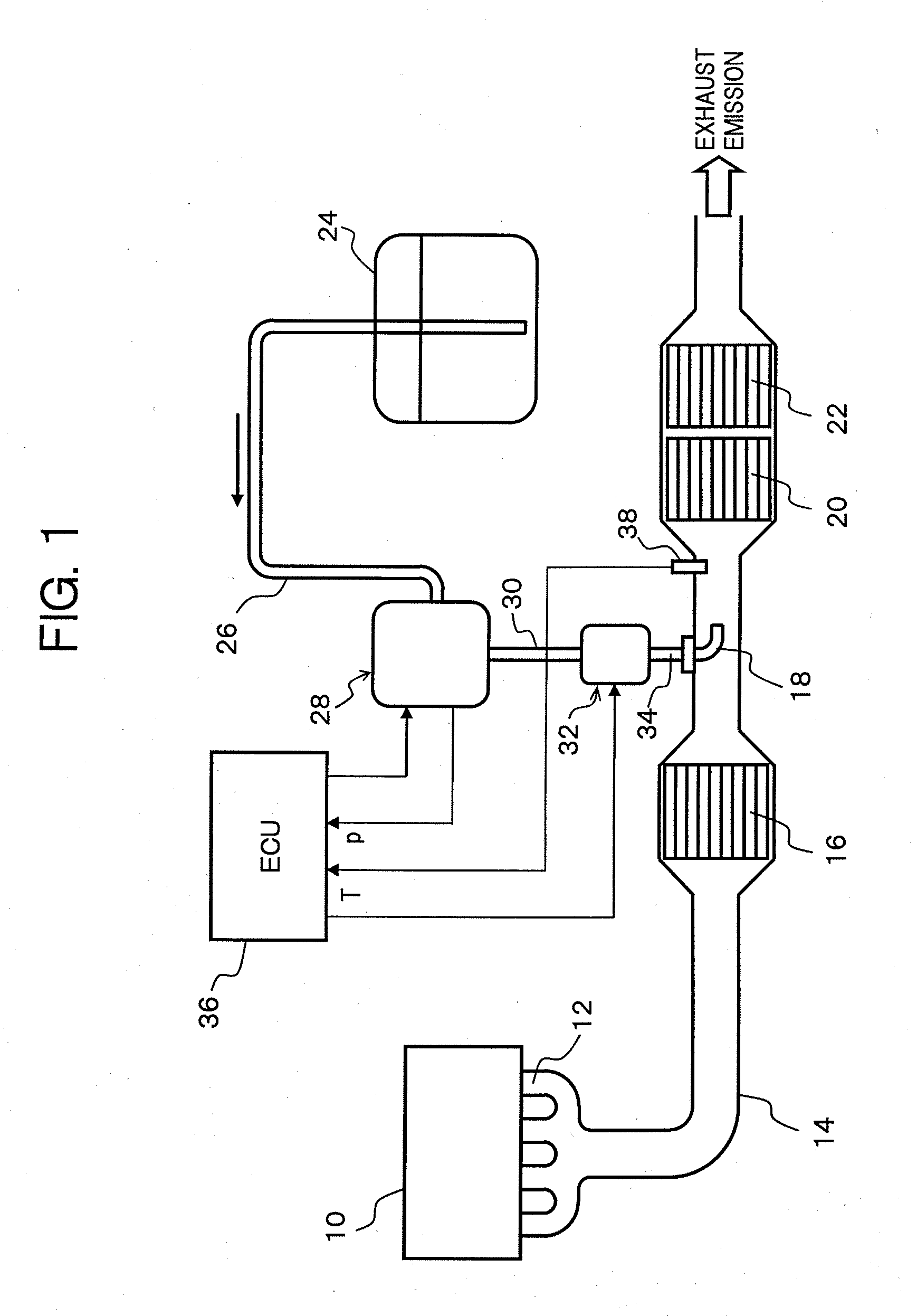
[0016]FIG. 1 shows an entire configuration of an exhaust emission purifying apparatus which uses the urea aqueous solution which is precursor of a liquid reducing agent, for purifying NOx contained in the engine emission by the catalytic-reduction reaction.

[0017]In an exhaust pipe 14 connected to an exhaust manifold 12 of an engine 10, there are disposed, along an exhaust emission flow direction, a nitrogen oxidation catalytic converter 16 which oxidizes nitrogen monoxide (NO) into nitrogen dioxide (NO2), an injection nozzle 18 which injection-supplies the urea aqueous solution, a NOx reduction catalytic converter 20 which reductively purifies NOx using ammonia obtained by hydrolyzing the urea aqueous solution, and an ammonia oxidation catalytic converter 22 which oxidizes ammonia passed through the NOx reduction catalytic converter 20.

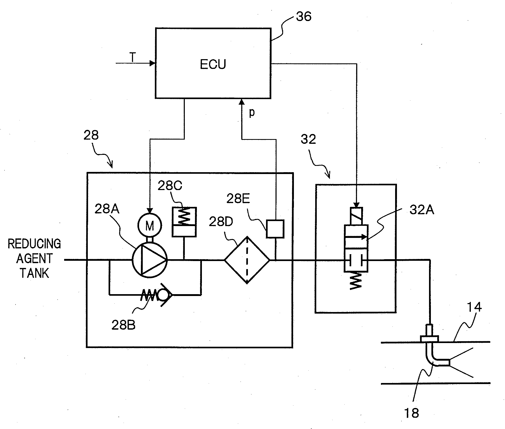
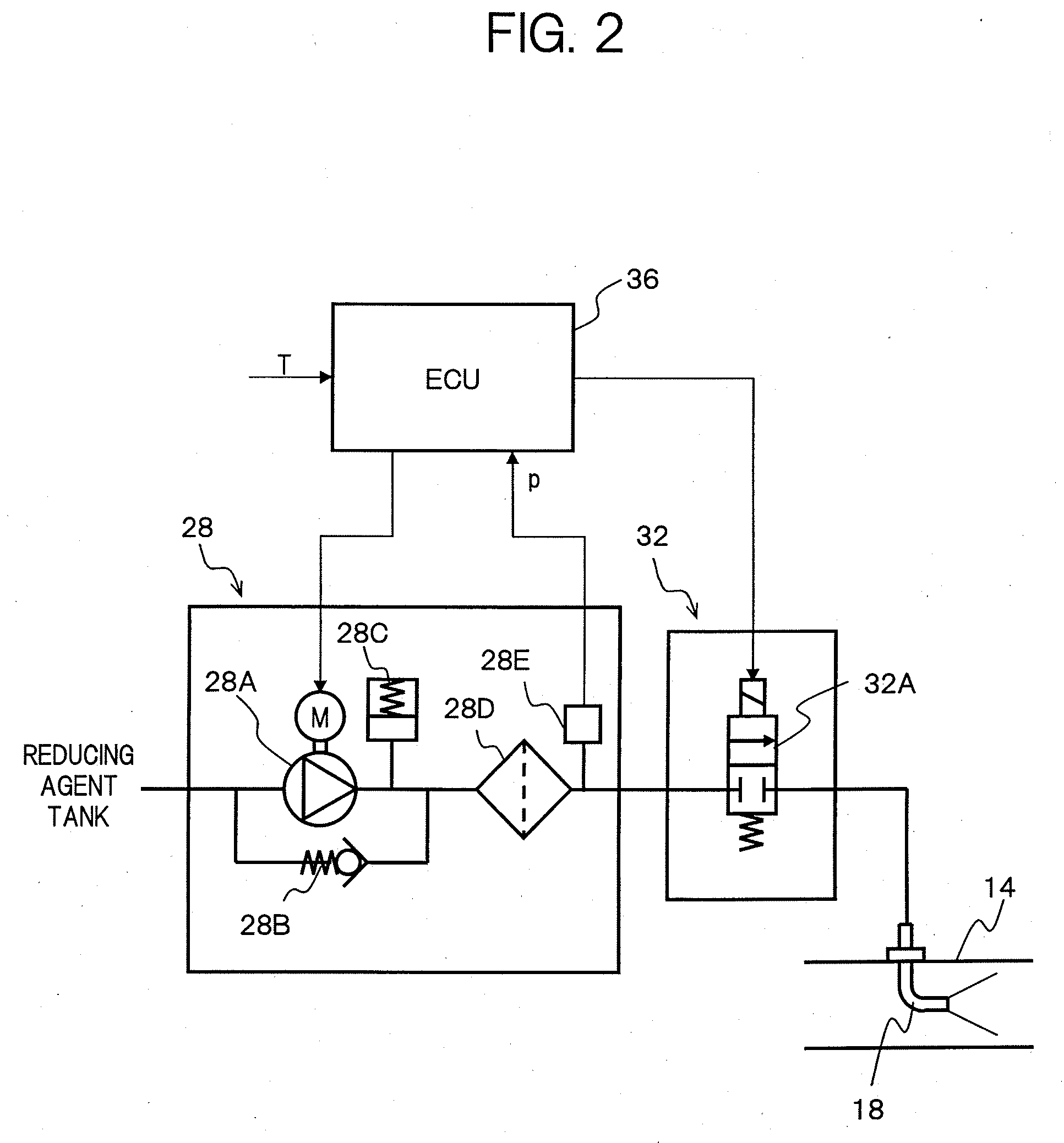
[0018]On the other hand, a reducing agent ...


PUM


Abstract

An exhaust emission purifying apparatus for an engine in which it is determined that a reducing agent supply system is clogged, which is arranged on the downstream of a pump carrying out suction and pumping of a liquid reducing agent out of a reducing agent tank, when a reduction in a pressure of the liquid reducing agent remaining in the downstream of the pump and also in the upstream of a flow control valve by an amount equal to or more than a first predetermined pressure does not occur until a cumulative injection amount obtained by sequentially integrating an injection amount of the liquid reducing agent computed in real time based on engine operating conditions reaches a predetermined amount after the pump has been temporarily stopped.

Description

[0001]This application is a continuation of PCT / JP2007 / 061636, filed on Jun. 8, 2007.BACKGROUND OF THE INVENTION[0002]1. Field of the Invention[0003]The present invention generally relates to an exhaust emission purifying apparatus for an engine (hereinafter, referred to as an exhaust emission purifying apparatus), which is provided for reductively purifying nitrogen oxides (NOx) in an exhaust emission of the engine and, more particularly, relates to a technology for determining with high accuracy whether or not a supply system of a liquid reducing agent or precursor thereof brings about clogging.[0004]2. Description of the Related Art[0005]As a catalytic purification system which purifies NOx contained in the exhaust emission of an engine, there has been proposed, in Japanese Laid-open (Kokai) Patent Application Publication No. 2000-27627, an exhaust emission purifying apparatus. In this exhaust emission purifying apparatus, a liquid reducing agent or precursor thereof (to be refer...

Claims


Application Information

Patent Timeline
IPC IPC(8): F01N3/20
CPCF01N3/208F01N11/00F01N2550/05F01N2560/06F01N2610/02F01N2610/1493F01N2900/0418F01N2900/08F01N2900/1808Y02T10/47Y02T10/24F01N13/0097Y02T10/12Y02T10/40
Inventor KATOU, TOSHIKAZUMATSUNAGA, HIDEKI
Owner NISSAN DIESEL MOTOR CO
Why Eureka
Try Eureka