
Spot Weld Gun

a technology of spot welding and gun, which is applied in the direction of resistance electrode holders, electrode features, manufacturing tools, etc., can solve the problems of cable power or signal transmission, more expensive in the first step, and difficulty in developing wireless power transmission, etc., and achieves the effect of convenient design

Inactive Publication Date: 2008-11-06
ABB (SCHWEIZ) AG
View PDF13 Cites 6 Cited by
  • Summary
  • Abstract
  • Description
  • Claims
  • Application Information

AI Technical Summary

Benefits of technology

The present invention solves problems in the design of spot weld guns by providing a rotating transformer to transport both the required power to the weld current and the required auxiliary power to the servo drives and other tools on the robot. The use of a rotating transformer allows for a more efficient use of power and makes it easier to change the tool being used. The secondary side of the transformer has a first module and a second module, which can be easily exchanged to change the required power. The power transmission comprises a weld transformer adapted to transform the power from the rotating transformer to a current suitable for spot welding. The invention also allows for the simultaneous control of the weld current and the servo drives, and provides a way to control the weld current during the idle phase of the spot weld gun. The use of a rotating transformer or a contactless rotating transformer simplifies the design of the transformer.

Problems solved by technology

A problem in connection with the use of a spot weld gun in a system having at least one rotatable joint is how to transport the required welding power over the rotating joint.
Transporting the power via a cable has drawbacks due to mechanical wear from the rotating joint.
A problem in connection with the introduction of a servo driven weld gun in a system having rotatable joints is how to provide the spot weld gun with the required electric auxiliary power as well as the required welding power.
When introducing wireless communication and power transmission technology, the servo loop requires additional transmission of power to run the motor which still requires auxiliary power transmission through cables and which will make the wireless power transmission more difficult to develop and more costly in the first step.
Using cables for power or signal transmission are also limiting the degree of movement of the spot weld gun.
It is a problem to take these limitations into consideration when controlling the spot weld gun on a robots arm.
Another problem of spot weld guns according to prior art is that the transformer used to generate the weld current is heavy and gives a lever movement as the spot weld gun is to be controlled in different movements of a robot.

Method used


Image

  • Spot Weld Gun
  • Spot Weld Gun
  • Spot Weld Gun

Examples


first embodiment

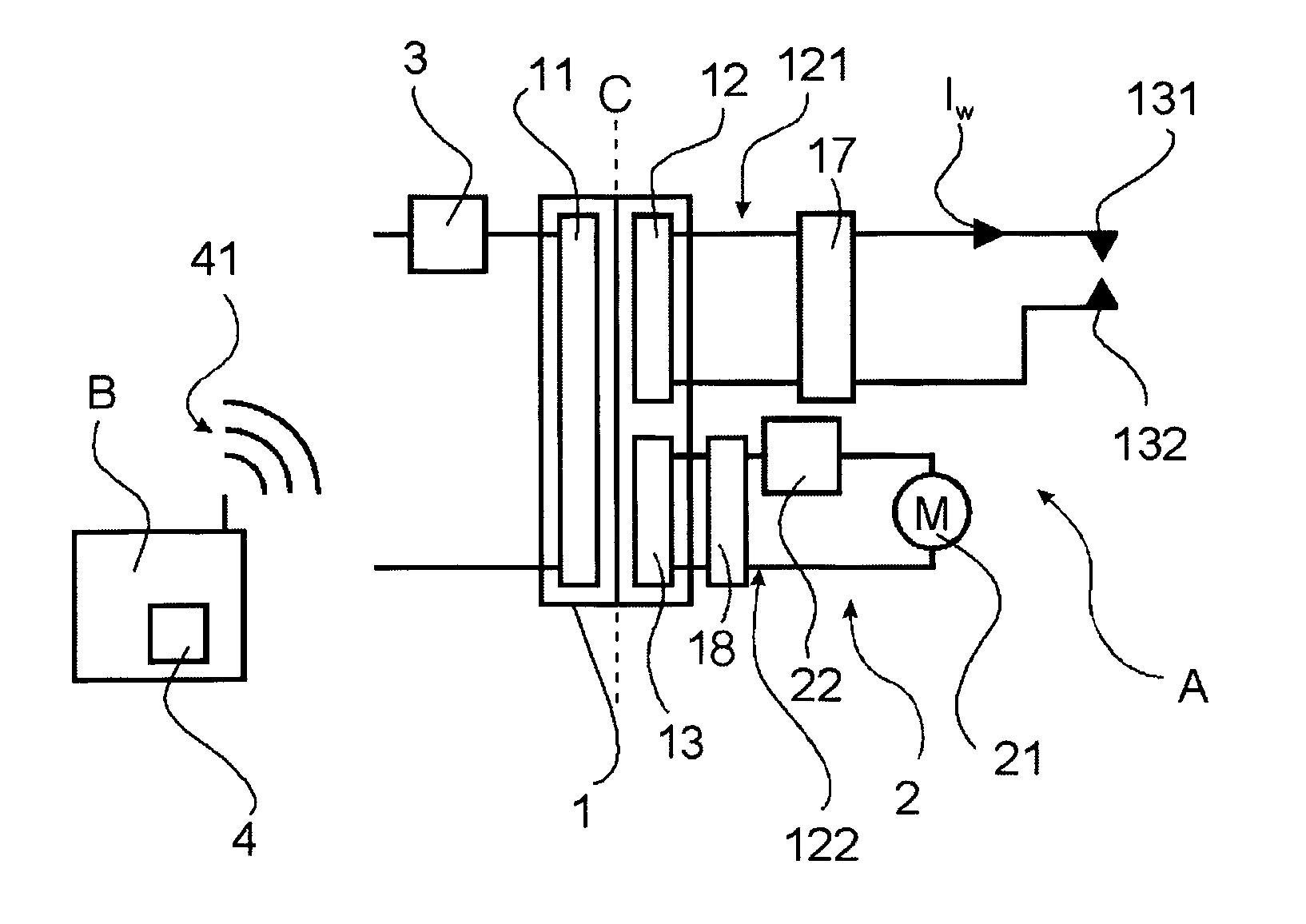
[0070] illustrated in FIG. 1 the weld timer 3 is positioned at the primary side 11 of the transformer 1. In this embodiment the primary converter of the transformer 1 is adapted to fully control the weld current

[0071]The present invention proposes two basic ways of controlling the weld current in a spot weld gun according to this first embodiment.

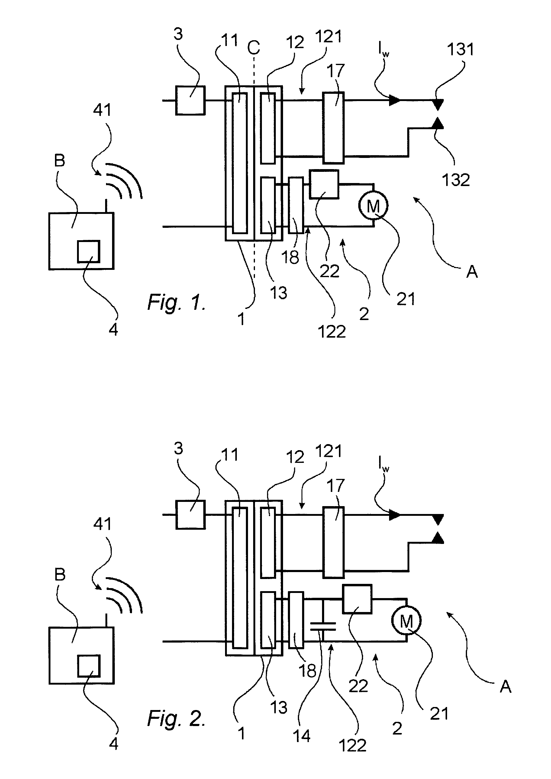
[0072]FIG. 1 shows that the weld current Iw is activated through the closing of the welding electrodes 131, 132 belonging to the weld gun A by means of the action from the servo motor 21.

[0073]FIG. 2 shows an auxiliary power energy storage 14 on the secondary side 12 of the transformer 1 adapted to provide any auxiliary power 122, and thus feed any servo drive 2 independently of the weld current Iw to control the weld or clamp force even during welding. It is proposed that a supercapacitor on the secondary side 12 is used as an auxiliary power energy storage 14.

[0074]The primary side 11 is adapted to feed the secondary side 12 with required...

second embodiment

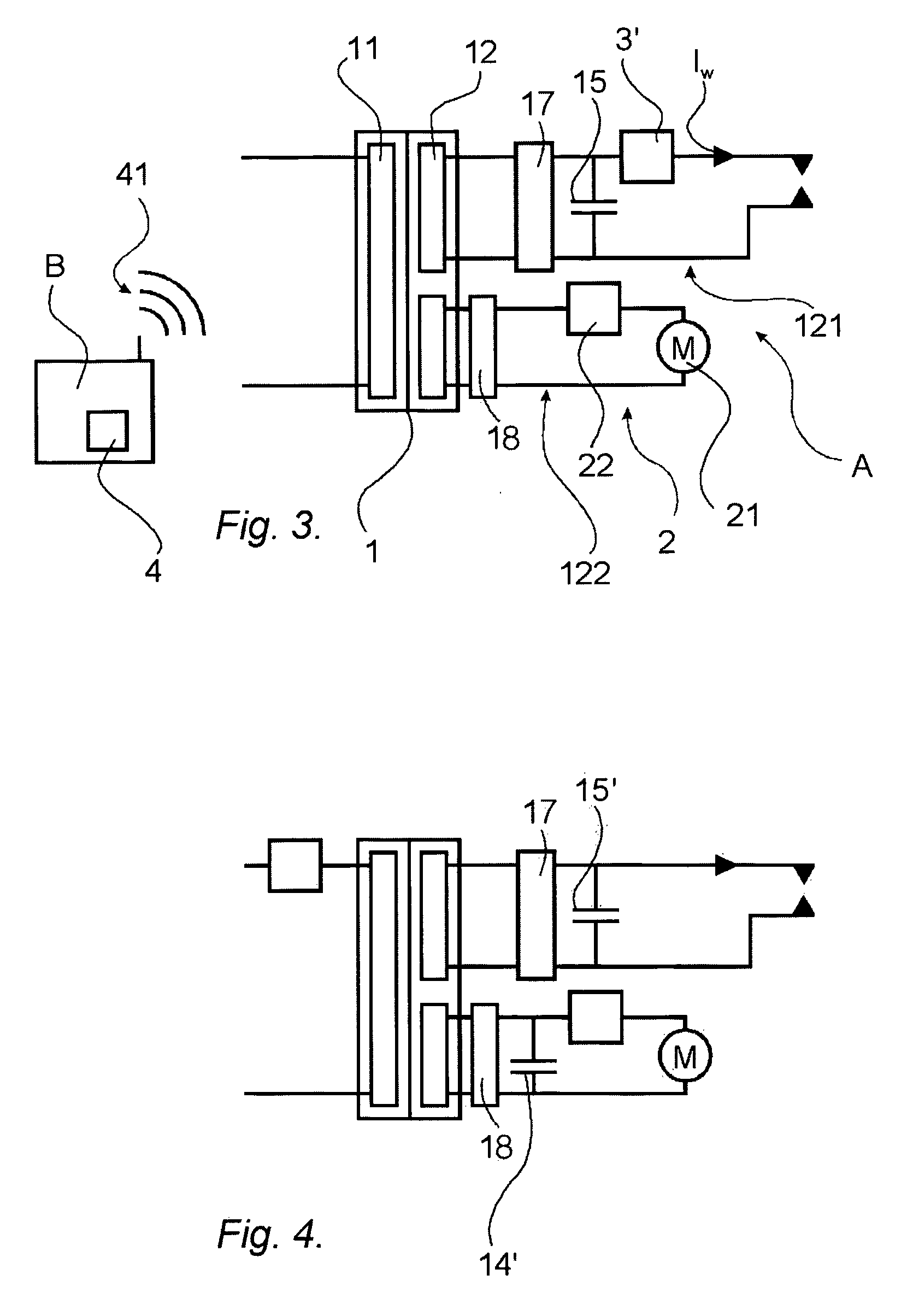
[0075]FIG. 3 illustrates the present invention where a welding power energy storage 15 belonging to the spot weld gun A and positioned at the secondary side 12 of the transformer 1 is adapted to provide the weld gun with required welding voltage. It is proposed that a large supercapacitor on the secondary side 12 is used as a welding power energy storage 15.

[0076]FIG. 4 shows that it is also possible to combine an auxiliary power energy storage 14′ with a welding power energy storage 15′. The auxiliary energy storage 14′ and / or the welding power energy storage 15′ may be realised through supercapacitors.

[0077]According to the second embodiment, shown in FIG. 3, it is proposed that the weld timer 3′ is positioned at the secondary side 12 of the transformer 1. In this embodiment the weld timer 3′ is adapted to fully control the weld current Iw.

[0078]The present invention proposes that the used transformer 1 is a rotating transformer, or even a contactless rotating transformer. Such a ...


PUM

PropertyMeasurementUnit
frequenciesaaaaaaaaaa
poweraaaaaaaaaa
weld currentaaaaaaaaaa

Abstract

A spot weld gun with thereto belonging power transmission being achieved by means of a rotating transformer including one primary side and one secondary side for transporting electrical power over a rotating joint. The one secondary side is adapted to provide both required power to the weld current and any required auxiliary power.

Description

FIELD OF INVENTION[0001]The present invention relates to a spot weld gun with thereto belonging power transmission, where the power transmission is achieved by means of a rotary transformer with a primary side and a secondary side. The present invention also relates to a weld system and number of methods to control the weld power of a spot weld gun.DESCRIPTION OF THE BACKGROUND ART[0002]During welding a spot weld gun requires a high energy current. To provide such a high current it is known to use a weld transformer. Such a weld transformer is for example shown in GB-patent no. 665 360. The spot weld gun comprises two electrodes, which are both supplied with current by a secondary winding of the weld transformer. The parts to be welded together are placed between the electrodes, and thereafter the transformer is energized and the welding is carried out. The transformer is only energized a short moment during the welding.[0003]It is known that in applications with a spot weld gun, su...

Claims


Application Information

Patent Timeline
Patent Type & Authority Applications(United States)
IPC IPC(8): B23K11/10B23K11/24B23K11/31
CPCB23K11/241B23K11/31
Inventor LUTHARDT, COLINSCHEIBLE, GUNTRAMFASTH, GREGERARANTIUS, JIMMYMORAEUS, JOHAN
Owner ABB (SCHWEIZ) AG
Learn More