Method and system for debug and test using replicated logic

a technology of replicated logic and logic, applied in logic circuits using specific components, instruments, program control, etc., can solve problems such as difficult to solve, debugging hardware design, and verification problems of complex circuit designs

Inactive Publication Date: 2008-10-30
SYNOPSYS INC
View PDF36 Cites 4 Cited by
  • Summary
  • Abstract
  • Description
  • Claims
  • Application Information

AI Technical Summary

Problems solved by technology

Continually advancing processing technology and the corresponding explosion in design size and complexity have led to verification problems for complex circuit designs, such as Application Specific Integrated Circuits (ASICs) that are difficult to solve using traditional simulation tools and techniques.
However, there are still problems with debugging the hardware design.
However, this is a difficult process and is often not effective, especially in the case of intermittent errors.
Errors that have already occurred are often difficult to repeat and reconstruct.

Method used


Image

  • Method and system for debug and test using replicated logic
  • Method and system for debug and test using replicated logic
  • Method and system for debug and test using replicated logic

Examples


Embodiment Construction

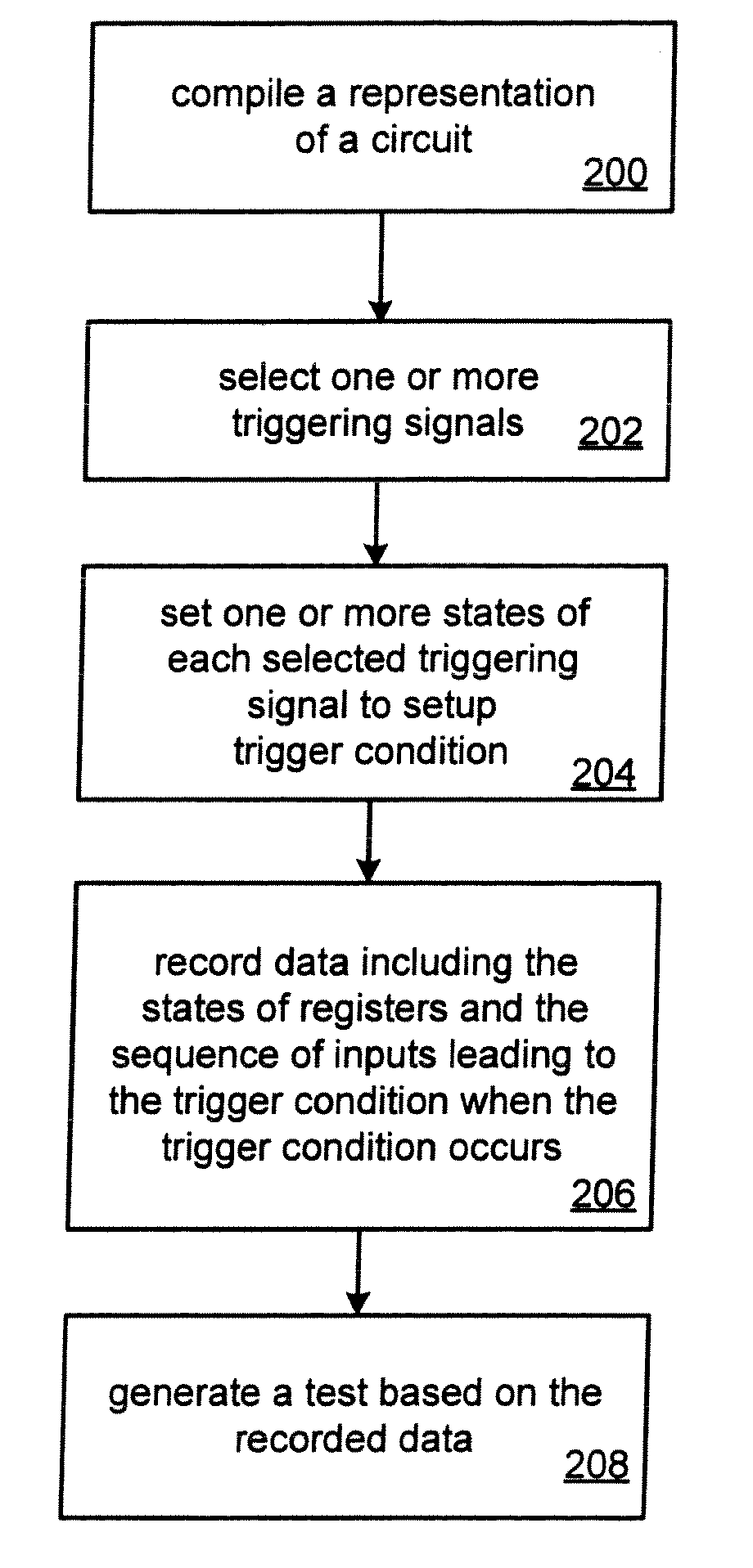
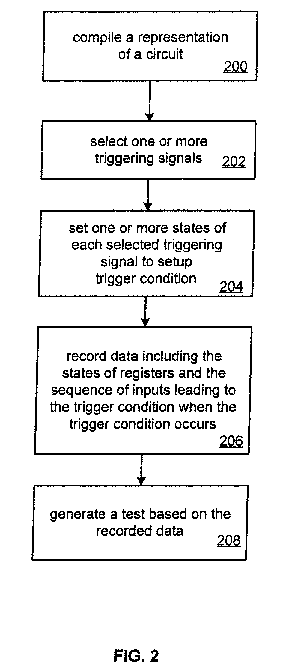
[0011]Embodiments of a system and method for debugging and testing using replicated logic are described. In the following description, numerous specific details are set forth. However, it is understood that embodiments of the invention may be practiced without these specific details. In other instances, well-known circuits, structures and techniques have not been shown in detail in order not to obscure the understanding of this description.

[0012]Reference throughout this specification to “one embodiment” or “an embodiment” means that a particular feature, structure, or characteristic described in connection with the embodiment is included in at least one embodiment of the invention. Thus, the appearances of the phrases “in one embodiment” or “in an embodiment” in various places throughout this specification are not necessarily all referring to the same embodiment. Furthermore, the particular features, structures, or characteristics may be combined in any suitable manner in one or mo...


PUM


Abstract

A method and system for debug and test using replicated logic is described. A representation of a circuit is compiled. The circuit includes a replicated portion and delay logic to delay inputs into the replicated portion. The circuit may also include trigger logic and clock control logic to enable execution of the replicated portion of the circuit to be paused when a trigger condition occurs. The compiled representation of the circuit may be programmed into a hardware device. A debugger may then be invoked. One or more triggering signals are selected. For each selected triggering signal, one or more states are selected to setup a trigger condition. The hardware device may then be run. The replicated portion of the circuit will be paused when the trigger condition occurs. The states of registers in the replicated portion of the circuit and the sequence of inputs that led to the trigger condition are recorded. This recorded data may then used to generate a test to be run on a software simulator when the circuit is modified.

Description

PRIORITY INFORMATION[0001]This application is a continuation of co-pending U.S. application Ser. No. 11 / 195,180, filed on Aug. 2, 2005, which is a continuation-in-part (CIP) of application Ser. No. 11 / 112,092, filed Apr. 22, 2005.TECHNICAL FIELD[0002]Embodiments of the invention relate to the field of debugging and testing integrated circuits, and more specifically to debugging and testing integrated circuits using replicated logic.BACKGROUND[0003]For the design of digital circuits, designers often employ computer aided techniques. Standard languages, such as Hardware Description Languages (HDLs), have been developed to describe digital circuits to aid in the design and simulation of complex digital circuits. As device technology continues to advance, various product design tools have been developed to adapt HDLs for use with newer devices and design styles.[0004]After the HDL code is written and compiled, the design of an integrated circuit (IC) or a system which includes multiple ...

Claims


Application Information

Patent Timeline
Patent Type & Authority Applications(United States)
IPC IPC(8): G06F17/50G01R31/30G01R31/317H01L21/82H03K19/173
CPCG01R31/3016G01R31/31705G06F17/5022G06F30/33
Inventor NG, CHUN KITLAROUCHE, MARIO
Owner SYNOPSYS INC
Why Eureka
Try Eureka