
Methods and devices for surgical drains with sensors

a technology of surgical drains and sensors, applied in the field of methods and devices for surgical drains with sensors, can solve the problems of compromise the survival of the organ, introduce vascular complications to the remaining portion of the organ, and test results have no dynamic valu

Inactive Publication Date: 2008-10-30
MANSOUR HEBAH NOSHY +1
View PDF0 Cites 32 Cited by
  • Summary
  • Abstract
  • Description
  • Claims
  • Application Information

AI Technical Summary

Problems solved by technology

Vascular complications may occur after organ transplantation which can compromise the survival of the organ and, in some cases, the patient.
Surgical resection of some organs such as the liver may introduce vascular complications to the remaining portion of the organ depending on the type and extent of the resection.
Also, these tests have no dynamic value since they indicate the liver condition only at the time when the blood sample is withdrawn.
Current organ monitoring technology offers probes that may require stitching or gluing to the tissue and therefore may not be easy to apply or remove especially if used inside the body.
Probe stitching to the surface of an organ may also disturb the local microvasculature, cause subcapsular hematoma, and interfere with the measurement of the probe.
This organ-invasive probe may cause bleeding, subcapsular hematoma, and may require extra care during insertion to avoid the puncture of underlying vessels.
Post-monitoring, the cuff probe may be difficult to remove and may left permanently around the vessel.
Optical tissue monitoring technology uses button-like probes are stitched to the tissue to measure its oxygen saturation using reflectance spectroscopy (e.g. Stitching can complicate probe application and removal.
Also, stitching may disturb the local microcirculation and introduces measurement errors.
Again, stitching can complicate probe application and removal and disturb the local microcirculation thereby introducing measurement errors.

Method used


Image

  • Methods and devices for surgical drains with sensors
  • Methods and devices for surgical drains with sensors
  • Methods and devices for surgical drains with sensors

Examples


Embodiment Construction

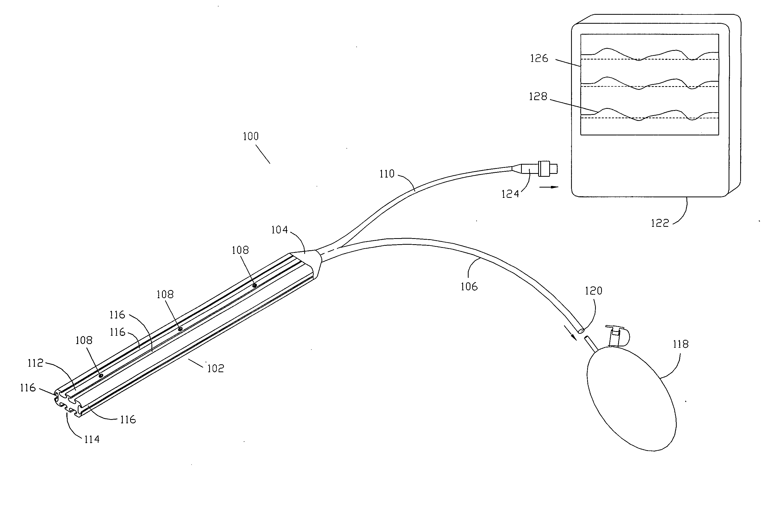
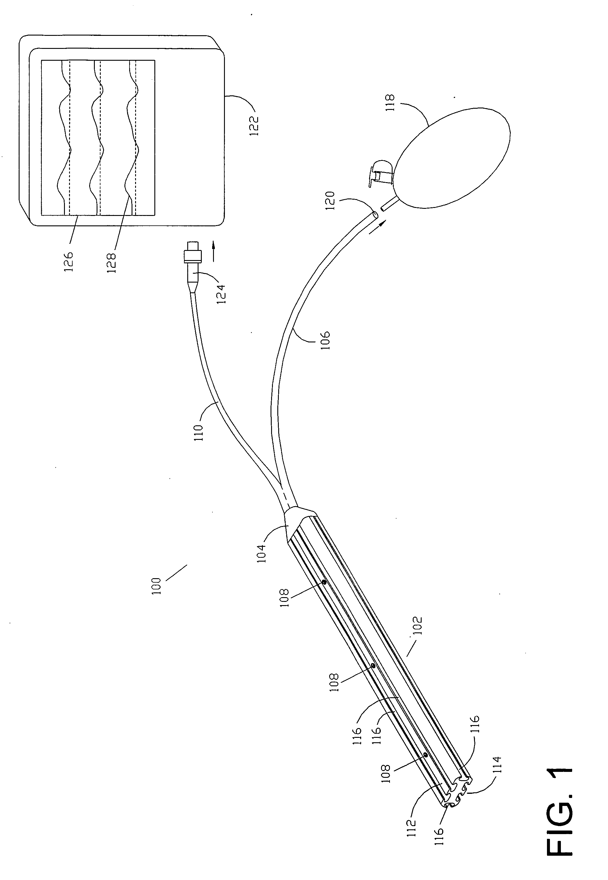
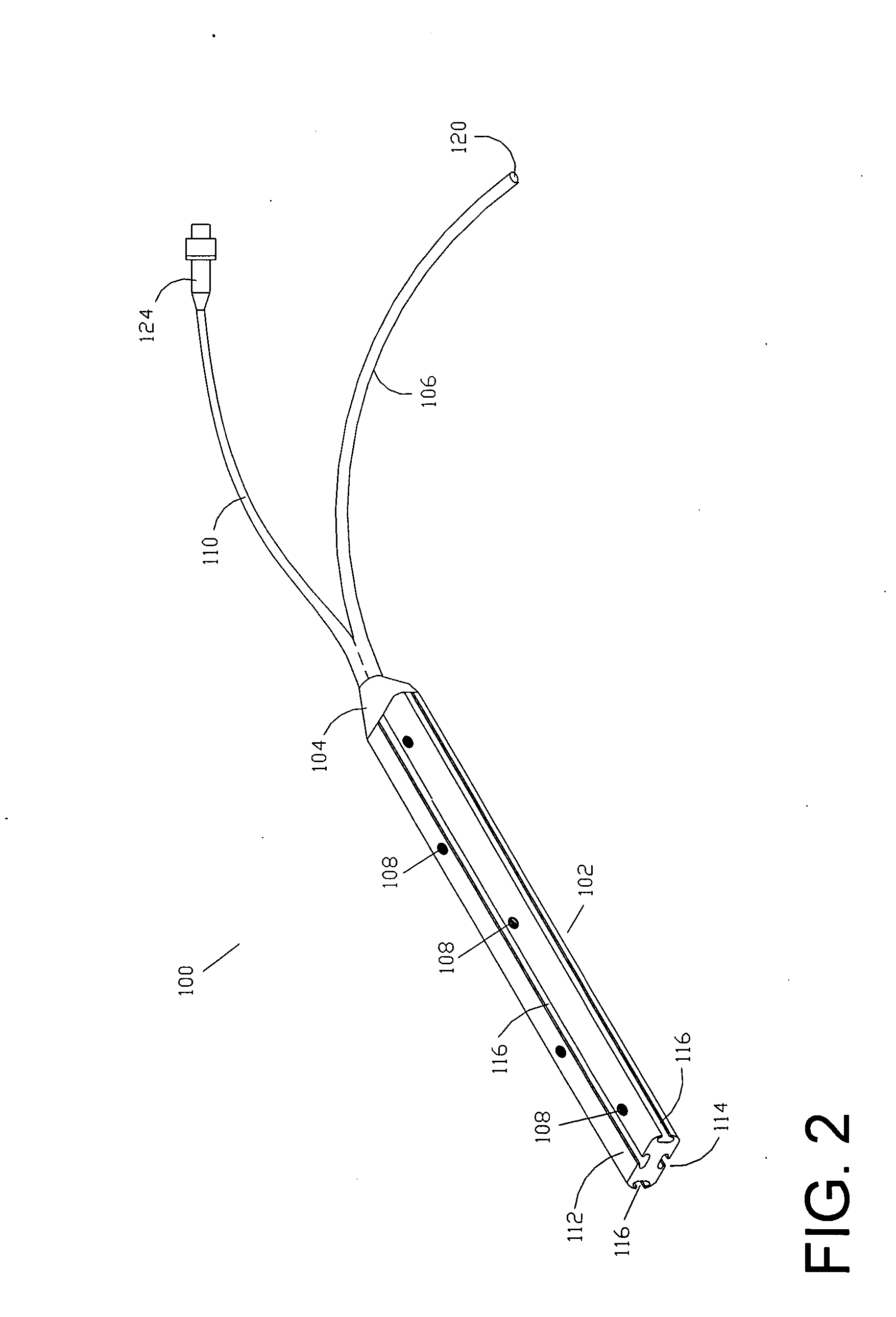
[0027]One embodiment of the drain probe 100 is shown in FIG. 1. The drain probe 100 may be comprised of a drain body 102, a fluid collection funnel 104, a fluid draining tube 106, sensors 108, and data cable 110. The drain body 102, collection funnel 104, and draining tube 106 may be made of flexible material such as medical-grade silicone or other elastomeres. The drain body may be made of a radiopaque material such as barium-loaded medical grade silicone for easier detection using radiographic techniques.

[0028]The drain body 102 may be preferably flat with a cross-section that is approximately rectangular in shape with a first surface 112 and a second surface 114. Alternatively, the cross-section of the drain body 102 may be square, elliptical, semi-circular, semi-elliptical, or trapezoidal in shape. A drain body 102 with a semi-elliptical or semi-circular cross-section may be advantageous in increasing the contact pressure between the sensors 108 and the adjacent tissue whereas t...


PUM


Abstract

The present invention is directed to a system and method for postoperative monitoring of the condition of a tissue or organ utilizing sensors that may be embedded in various types of surgical drains. The system is comprised of a probe and a monitoring unit. The probe may include a surgical drain with fluid draining channels housing one or more sensors to measure various parameters of the adjacent tissue. The monitoring unit which controls the sensors of the probe may include a processor to process, record and display the measured parameters. This system may be valuable for monitoring transplanted organs and tissue grafts during the critical postoperative period when most of the clinical complications, such as vascular thrombosis, may occur.

Description

CROSS-REFERENCE TO RELATED APPLICATION(S)[0001]This application claims priority to U.S. Provisional Patent Application 60 / 926,641 filed Apr. 28, 2007, entitled Methods and Devices for Surgical Drains with Sensors, the entire contents of which are incorporated herein by reference.FIELD OF THE INVENTION[0002]The present invention is directed to devices and methods of using a surgical drain to monitor internal tissue condition, and more particularly to a surgical drain having at least one sensor for monitoring the condition of a tissue proximate to the surgical drain.BACKGROUND OF THE INVENTION[0003]Vascular complications may occur after organ transplantation which can compromise the survival of the organ and, in some cases, the patient. Surgical resection of some organs such as the liver may introduce vascular complications to the remaining portion of the organ depending on the type and extent of the resection. This makes it important to monitor the surgically affected organs during t...

Claims


Application Information

Patent Timeline
IPC IPC(8): A61B5/05A61M27/00
CPCA61B5/14542A61B5/1459A61B5/413A61B5/445A61B5/6852A61M27/00
Inventor MANSOUR, HEBAH NOSHYMIKHAIL, MONA BAHGAT ZAKI
Owner MANSOUR HEBAH NOSHY
Learn More