Optical switch

a technology of optical switch and switch body, applied in the field of optical communication system, can solve the problems of crosstalk effect, increase in production cost, and reduce signal strength, and achieve the effect of reducing production cos

Inactive Publication Date: 2008-10-30
ARCADYAN
View PDF4 Cites 1 Cited by
  • Summary
  • Abstract
  • Description
  • Claims
  • Application Information

AI Technical Summary

Benefits of technology

[0013]The present invention is directed to an optical switch for reducing production costs.
[0014]The present invention is further directed to an optical switch for improving reliability.
[0015]The present invention is further directed to an optical switch for undergoing strict condition inspection easily and successfully.
[0022]In view of the foregoing, the present invention is able to directly mount the two output optical fibers (the first and the second optical fibers) in the V-grooves on the single alignment head formed by precision processing. Through a simple assembling process, the precise alignment of the input optical fiber (the third optical fiber) is completed, thus simplifying the time-consuming alignment process of the conventional optical fibers. Moreover, the present invention may utilize the displacing means along with the wedge having the incline for meeting the requirements for horizontal movement on an axial plane between the input optical fiber and the two output optical fibers. Furthermore, the displacing means providing a small amount of displacement can be adopted to induce large displacement of the optical fiber through increasing a slope of the incline of the wedge.

Problems solved by technology

The insertion loss may reduce the strength of the signals, while reflected signals may result in crosstalk effects.
Due to a small position tolerance of the optical fibers of the optical switch, the alignment of the optical fibers is rather time-consuming during the process of manufacturing the optical switch, leading to an increase in the production costs.
In spite of omitting the alignment between two alignment heads, the single alignment head having the through hole in the diamond shape is still not able to alleviate difficulties of assembling the optical fibers in an effective manner.
However, said patent is not conducive to reducing the complexity of assembling the optical fibers.

Method used


Image

  • Optical switch
  • Optical switch
  • Optical switch

Examples


Embodiment Construction

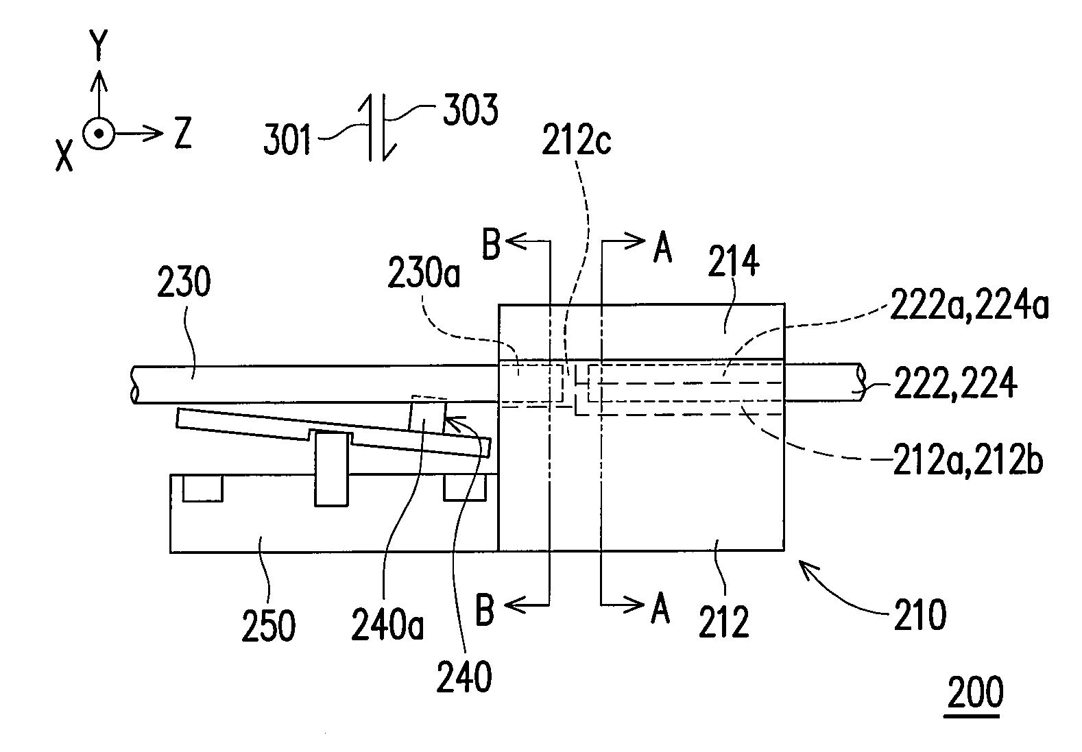
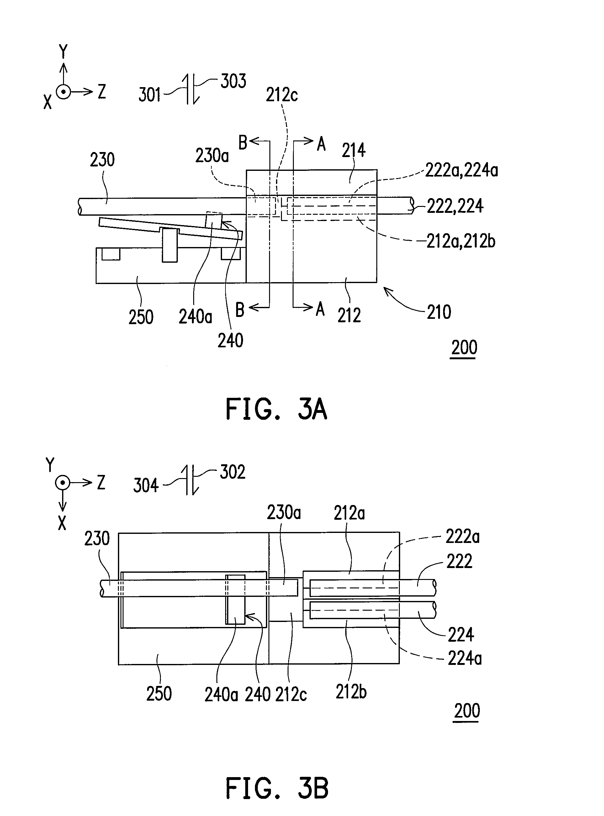
[0035]Referring to FIGS. 3A to 3D, an optical switch 200 of the present embodiment includes an alignment head 210, a first fiber 222, a second fiber 224 and a third fiber 230. All of the components are installed in a housing (not shown).

[0036]The alignment head 210 has a base 212 and a cover 214. The base 212 has a first V-groove 212a, a second V-groove 212b, and a trench 212c linked to the first and the second V-grooves 212a and 212b.

[0037]An end 222a of the first fiber 222 is mounted in the first V-groove 212a and faces the trench 212c. An end 224a of the second fiber 224 is mounted in the second V-groove 212b and faces the trench 212c. The cover 214 is mounted on the base 212 to fix the ends 222a and 224a of the first and the second V-grooves 222 and 224. An end 230a of the third fiber 230 is located in the trench 212c and is capable of being moved in the trench 212c under control of the cover 214c. In a first condition, the end 230a of the third fiber 230 is aligned to the end ...


PUM


Abstract

An optical switch including an alignment head, a first fiber, a second fiber, a third fiber, a wedge, and a displacing means is provided. The alignment head has a base and a cover. The base has a first V-groove, a second V-groove, and a trench linked to the first and the second V-grooves. An end of the first fiber and that of the second fiber are mounted in the first and the second V-grooves, respectively. The cover is mounted on the base to secure the ends of the first and the second V-grooves. An end of the third fiber located in the trench is aligned to that of the first fiber. The wedge located beside the base has an incline. The displacing means set under the wedge is capable of aligning the end of the third fiber to that of the second fiber by moving the wedge.

Description

CROSS-REFERENCE TO RELATED APPLICATION[0001]This application claims the priority benefit of Taiwan application serial no. 96114545, filed Apr. 25, 2007. All disclosure of the Taiwan application is incorporated herein by reference.BACKGROUND OF THE INVENTION[0002]1. Field of the Invention[0003]The present invention relates to an optical communication system, and more particularly to an optical switch employed in the optical communication system.[0004]2. Description of Related Art[0005]With rapid development in fiber optics communication, optical fibers are widely embedded all over the world, so as to provide wider bandwidth and better reliability than copper wires, microwave relays and satellites do. An optical communication system includes a large number of optical switches for transmitting signals through specific network routes. The optical switch is capable of selecting one of the optical fibers and alternatively aligning ends of two optical fibers, such that light beams can be t...

Claims


Application Information

Patent Timeline
Patent Type & Authority Applications(United States)
IPC IPC(8): G02B6/26
CPCG02B6/3508G02B6/355G02B6/3564
Inventor YEN, KUO-AN
Owner ARCADYAN
Why Eureka
Try Eureka