Semi-full helical luminous electronic energy-saving lamp

a technology of electronic energy saving lamps and semi-full helical luminous, which is applied in the direction of discharge tubes/lamp details, discharge tubes luminescnet screens, gas-filled discharge tubes, etc., can solve the problems of reducing the pass rate of the enclosure, the inability to adapt the design of the tube stem to automation, and the waste of a lot of material for the enclosure, etc., to achieve good quality consistency, improve the pass rate of fabrication, and the effect of sufficient spa

Inactive Publication Date: 2008-10-30
CRYSTAL GREEN LIGHTING
View PDF21 Cites 2 Cited by
  • Summary
  • Abstract
  • Description
  • Claims
  • Application Information

AI Technical Summary

Benefits of technology

[0011]A position limitation board is provided in the inclined tube hole to limit the depth of insertion of the straight section of the tube. This minimizes heat transfer from the hot tube end into the enclosure where the ballast resides. The heat reduces the reliability and life of the ballast. A hole is formed on the position limitation board for passing through the stem of tube.
[0014]Some advantages of the present invention are: (1) Since the stem is enclosed or clipped on the tube straight section, which is not deformed because it is not processed, there is a good quality consistency. (2) By making use of the sharp inward elbow bending, sufficient space is created for the enclosure assembly process. Therefore, the pass rate of fabrication is improved significantly. (3) In addition, the enclosure size of the entire lamp after inward bending is now dependent on the ballast's size. In earlier designs, the enclosure size was dependent on what size the helical tube could be packaged in, which was much larger without the inward elbow bend. Thus, the costs of enclosure materials can be saved.

Problems solved by technology

However, the following problems exist with an electronic energy-saving lamp with such a construction: (1) The outer diameter of the enclosure needs to be larger than the external outer diameter of the tube in order to fully enclose it, so a lot of material for the enclosure is wasted.
So during lamp fabrication, the process of enclosing the tube stem decreases the pass rate due to quality control issues.
(3) Finally, this tube design is difficult to adapt to automation again due to the quality consistency issue.
Although this tube structure solved the problems of a tube stem enclosure that existed in the lamp fabrication process, the fabrication costs are relatively higher as compared with the former design.

Method used


Image

  • Semi-full helical luminous electronic energy-saving lamp
  • Semi-full helical luminous electronic energy-saving lamp
  • Semi-full helical luminous electronic energy-saving lamp

Examples


Embodiment Construction

[0024]To facilitate the understanding of the technical means, creative features, and effectiveness realized in the present invention, preferred embodiments of the invention are further described below in combination with the specific drawing figures.

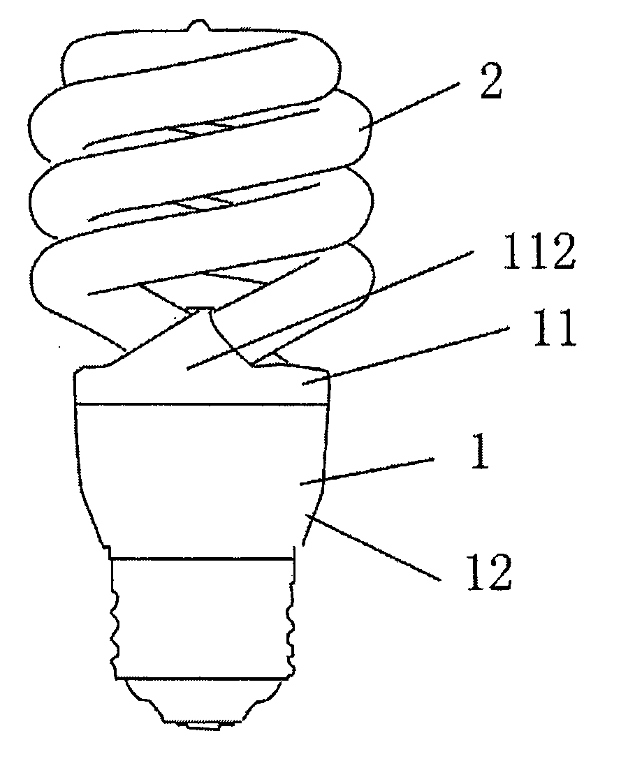
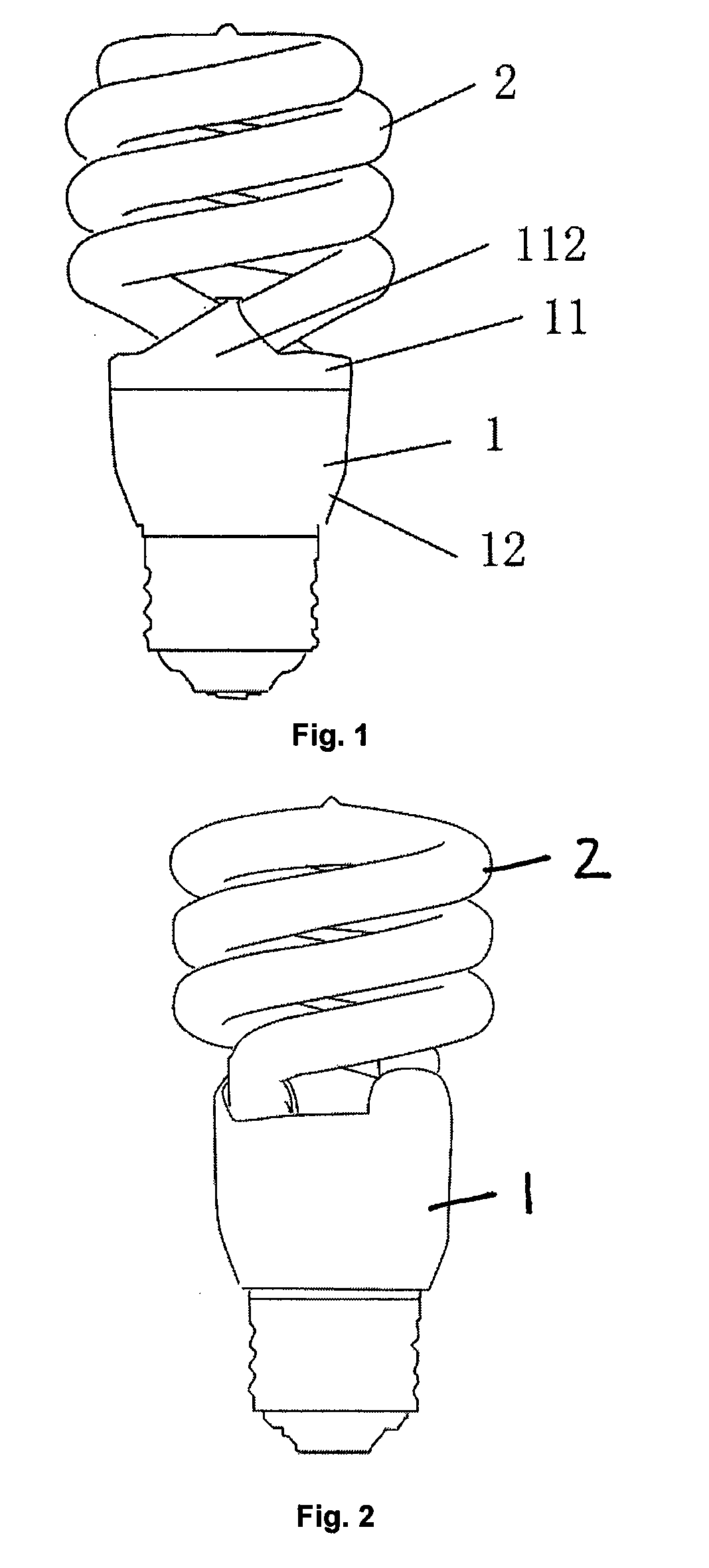
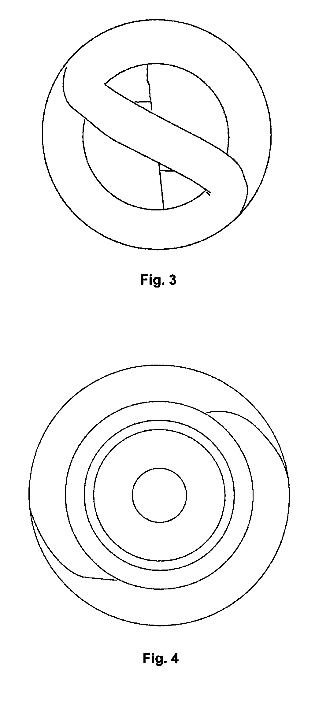
[0025]The present invention generally relates to a compact fluorescent lamp (CFL) and the tube used in such a lamp. In the preferred embodiment shown in FIGS. 1, 2, 3 and 4, the semi-full helical luminous electronic energy-saving lamp includes an enclosure 1, a coiled, helical shape tube 2, and a lamp base having external threads (not shown) with metallic contacts to be screwed into a standard incandescent light bulb socket. The shape of the helical tube has two features—a straight section diverging from the continuous curve of the helix, and a sharp elbow forming a 180° backward bend.

[0026]For example, in FIGS. 7 and 8, the structure at the connection between the end of the tube 2 and the enclosure 1 is straight section 21. One end of t...


PUM


Abstract

A semi-full helical luminous electronic energy-saving tube and an electronic energy-saving lamp using the tube are disclosed. The structure at the connection between the end of tube and the enclosure is a straight section. An inward bend of the straight section is achieved via an interface point between the straight section and the helical portion of the tube. The interface point includes a sharp, V-shaped 180° backward bend. By making use of the sharp inward bend, a sufficient space is left for the enclosure process.

Description

CLAIM OF FOREIGN PRIORITY UNDER 35 U.S.C. §119[0001]This application claims priority under 35 U.S.C. § 119 from Chinese Patent Application No. 200720069619.3 by Robin Zheng, filed Apr. 29, 2007, and from Chinese Patent Application No. 200720073207.7 by Chun-Tsun Chen, filed Aug. 1, 2007, which disclosures are hereby incorporated by reference.BACKGROUND OF THE INVENTION[0002]The present invention relates to an electronic energy-saving lamp, and specifically relates to a semi-full helical luminous electronic energy-saving tube and the electronic energy-saving compact fluorescent lamp (CFL) containing the luminous tube.[0003]The electronic energy-saving lamp generally consists of an enclosure, a lamp base, a tube, and a ballast. Among them, the tube and lamp base are fixed on the enclosure and the ballast is installed inside the enclosure.[0004]There are various types of tubes used in electronic energy-saving lamps. For example, Chinese Patent No. 02216802.8 discloses an electronic ene...

Claims


Application Information

Patent Timeline
IPC IPC(8): H01J1/62H01J17/16
CPCH01J61/327
Inventor CHEN, CHUN-TSUNZHENG, ROBIN
Owner CRYSTAL GREEN LIGHTING
Why Eureka
Try Eureka