Saw Blade And A Method Of Manufacturing A Saw Blade

a manufacturing method and technology of a saw blade, applied in the field of saw blades, can solve the problems of blade destruction, and achieve the effects of avoiding warping of the substrate and/or the neck, reducing the risk of accidents, and reducing the risk of blade damag

Inactive Publication Date: 2008-10-30
INDOCEAN DIAMOND TOOLS BERMUDA
View PDF21 Cites 0 Cited by
  • Summary
  • Abstract
  • Description
  • Claims
  • Application Information

AI Technical Summary

Benefits of technology

[0019]The grinding included in the prior art methods is particularly difficult since the simultaneous grinding of a hard material (the tooth) and a soft material (the neck) with the same tool, e.g. a grinding disc, is difficult and often causes the soft material to clog the tool, which must be designed with main focus on the hard material. An advantage of the invention is that the adjacent surface of the tooth need not be grinded after fastening it to the neck. The troublesome simultaneous grinding of the adjacent surface and the tooth neck according to prior art may be thus avoided.
[0020]Preferably a surface intended for sliding against a contact area associated with an adjacent saw blade is provided on the saw blade adjacent to the tooth necks. The surface provides a steady abutment so that the two saw blades may slide against each other in a steady way and with minimum wear. Still more preferably said surface is provided on the saw blade by machining at least a peripheral part of the substrate before said step of fastening the teeth. The protection surfaces of the tooth necks and the substrate periphery are peripheral parts of the substrate. The machining should be made on the protection surfaces of the tooth necks and / or on the periphery of the substrate. After the fastening of the teeth the saw blade is thus ready for use, thus the manufacturing of the saw blade becomes efficient with few steps. If desired a final grinding of the cutting surfaces of the teeth may be made. No machining of the substrate, necks or adjacent surface of the tooth is required after fastening the tooth. If the fastening of the tooth is accomplished by a heat adding method, such as soldering, brazing or welding, some cooling at the brazing spot is preferably applied to avoid warping of the substrate and / or neck.
[0021]Preferably the tooth is provided with a smooth adjacent surface, the tooth being placed on the neck in such a position that the distance from the adjacent surface to the protection surface will be 0.005 to 0.10 mm. As explained above this placement of the tooth provides for a good protection of the tooth and narrow cutting characteristics of the saw blade.
[0022]These and other aspects of the invention will be apparent from and elucidated with reference to the embodiments described hereafter.

Problems solved by technology

Thus the risk of accidents and destruction of the blade is decreased, particularly in applications were the blade is exposed to forces in varying directions.

Method used


Image

  • Saw Blade And A Method Of Manufacturing A Saw Blade
  • Saw Blade And A Method Of Manufacturing A Saw Blade
  • Saw Blade And A Method Of Manufacturing A Saw Blade

Examples


Embodiment Construction

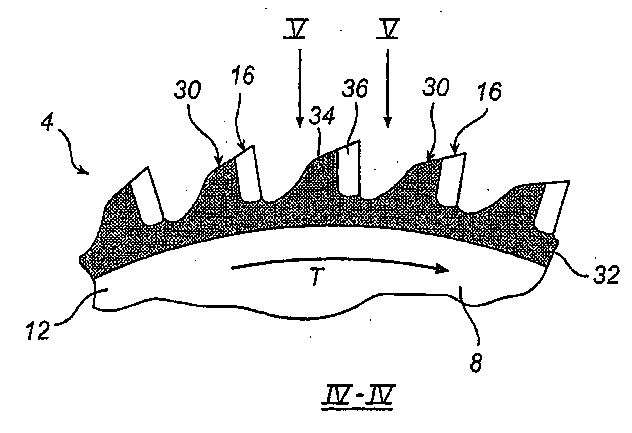
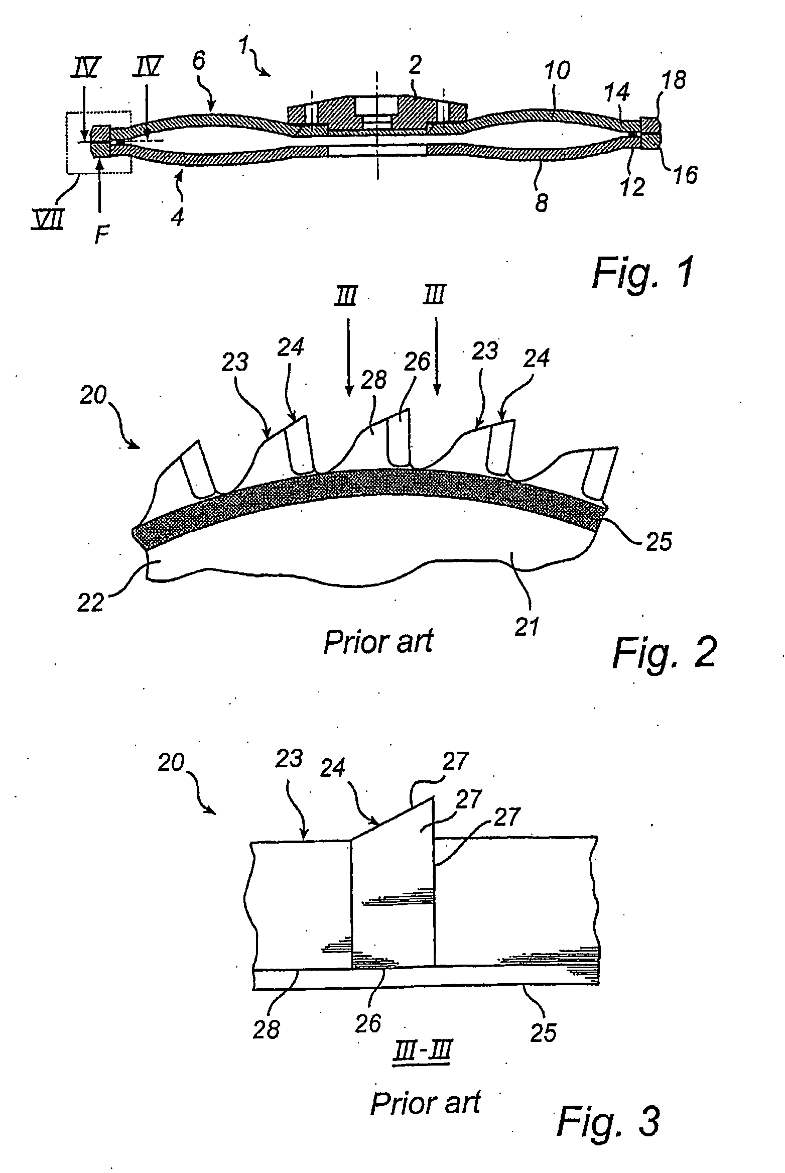
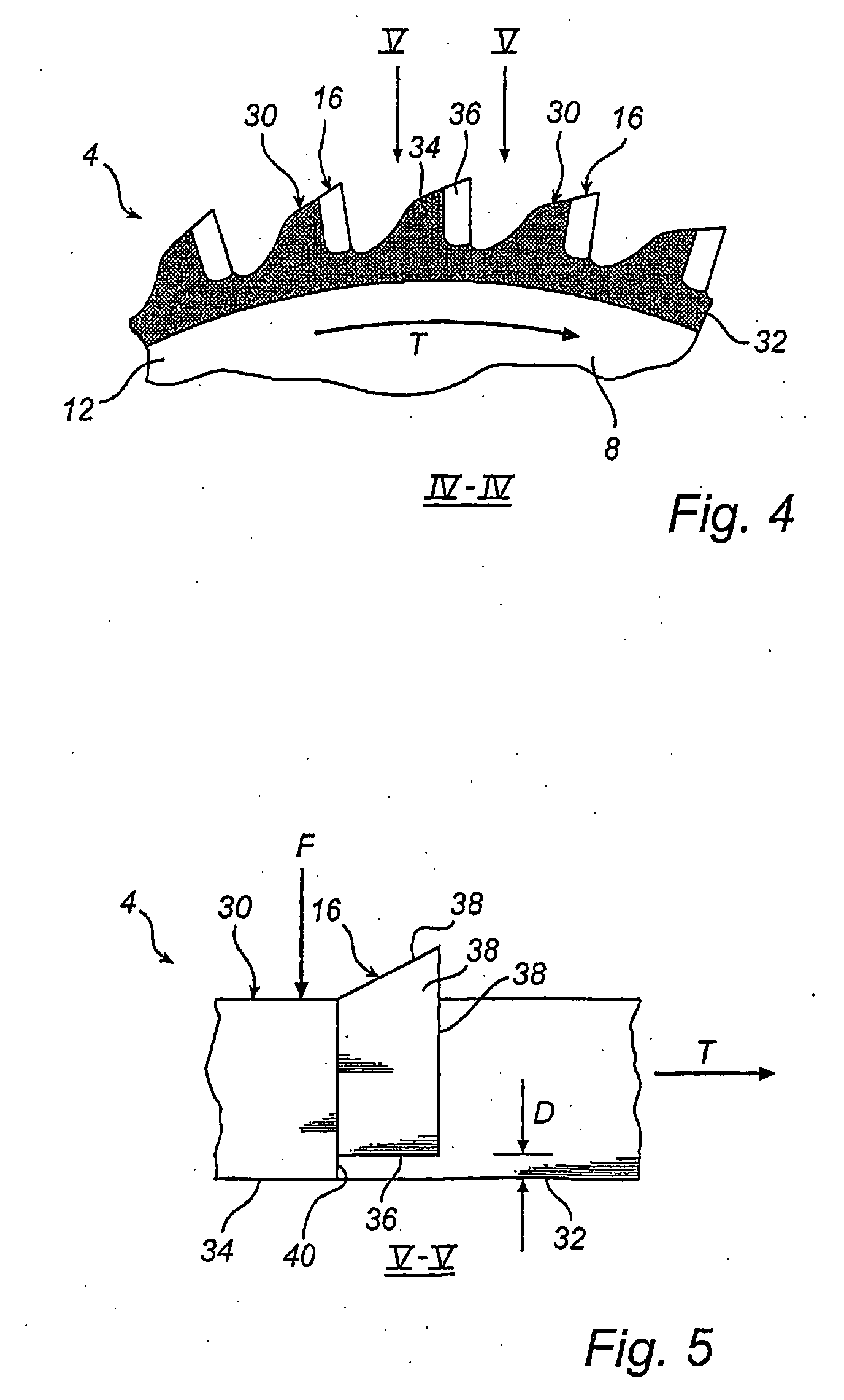
[0036]FIG. 1 shows, in section, a saw unit 1 for mounting on a twin blade cutter. The saw unit 1 comprises a hub 2, a first saw blade 4 which can be rotated in a first rotational direction and a second saw blade 6 which can be rotated in another rotational direction being opposite and parallel to said first direction. The first saw blade 4 comprises a blade substrate in the form of mild steel circular disc 8. The second saw blade 6 comprises a similar blade substrate in the form of a circular disc 10. At the periphery 12 of the first disc 8 first teeth 16 are fastened. At the periphery 14 of the second disc 10 second teeth 18 are fastened. The teeth 16, 18 are made from a hard material, such as a sintered metal containing wolfram, a ceramic or any other material suitable for the application, and are brazed to the respective mild steel discs 8, 10.

[0037]As is indicated in FIG. 1 the saw blades 4, 6 are slightly curved and bent towards each other. The hub 2 holds the saw blade 6 in su...


PUM

PropertyMeasurementUnit
Lengthaaaaaaaaaa
Areaaaaaaaaaaa

Abstract

A saw blade (4) for a machine operating with adjacent saw teeth traveling in two opposite and parallel directions comprises a blade substrate, teeth (16), and tooth necks (30) formed at the periphery of the substrate for holding the teeth (16) in place. Each tooth neck (30) has a protection surface (34), which is located in a plane that is parallel to the plane of the blade substrate (8), for protecting the tooth (16) against impact with any part of said adjacent saw blade. Each tooth (16) is located on the respective neck (30) in such a way that the tooth (16) is displaced from the protection surface (34) and from the adjacent saw blade in a direction normal to the plane of the protection surface (34).

Description

FIELD OF THE INVENTION[0001]The present invention relates to a saw blade for a machine operating with adjacent saw teeth traveling in two opposite and parallel directions, said saw blade comprising a blade substrate, teeth, and tooth necks formed at the periphery of the substrate for holding the teeth in place, the saw blade having a surface intended for sliding against a contact area associated with an adjacent saw blade.[0002]The present invention further relates to a method of manufacturing a saw blade for a machine operating with adjacent saw teeth traveling in two opposite and parallel directions, said saw blade comprising a blade substrate, teeth, and tooth necks formed at the periphery of the substrate for holding the teeth in place.BACKGROUND OF THE INVENTION[0003]Saws using two adjacent, circular saw blades are known from US 963,520 to Costello. The two blades rotate round a common axis but in different directions which makes the sawing easier and the risk of sudden strokes...

Claims


Application Information

Patent Timeline
IPC IPC(8): B27B33/02B23D63/00B23DB23D45/10B23D61/02B23D61/04B23D65/00
CPCB23D61/025B23D45/10B23D61/04B23D65/00Y10T83/9319Y10T83/9346Y10T83/935Y10T83/9367Y10T83/9403
Inventor ERICSSON, HANS
Owner INDOCEAN DIAMOND TOOLS BERMUDA
Why Eureka
Try Eureka