
Vehicle environment monitoring apparatus

a technology for monitoring apparatus and vehicle environment, applied in image analysis, scene recognition, instruments, etc., can solve the problems of increased cost and complicated structur

Active Publication Date: 2008-10-23
ARRIVER SOFTWARE AB
View PDF5 Cites 34 Cited by
  • Summary
  • Abstract
  • Description
  • Claims
  • Application Information

AI Technical Summary

Benefits of technology

[0007]In view of the foregoing, an object of the present invention is to solve the above-described problems and to provide a vehicle environment monitoring apparatus, a vehicle environment monitoring program and a vehicle environment monitoring method capable of detecting a monitored object in an environment around a vehicle by separating the same from a background, with a simple structure having a single camera mounted on the vehicle.

Problems solved by technology

When detecting the distance from the monitored object based on the parallax as described above, it is necessary to provide two cameras, which means an increased cost and a complicated structure and also requires a troublesome setting job to ensure precise adjustment of the optical axes of the two cameras.

Method used


Image

  • Vehicle environment monitoring apparatus
  • Vehicle environment monitoring apparatus
  • Vehicle environment monitoring apparatus

Examples


Embodiment Construction

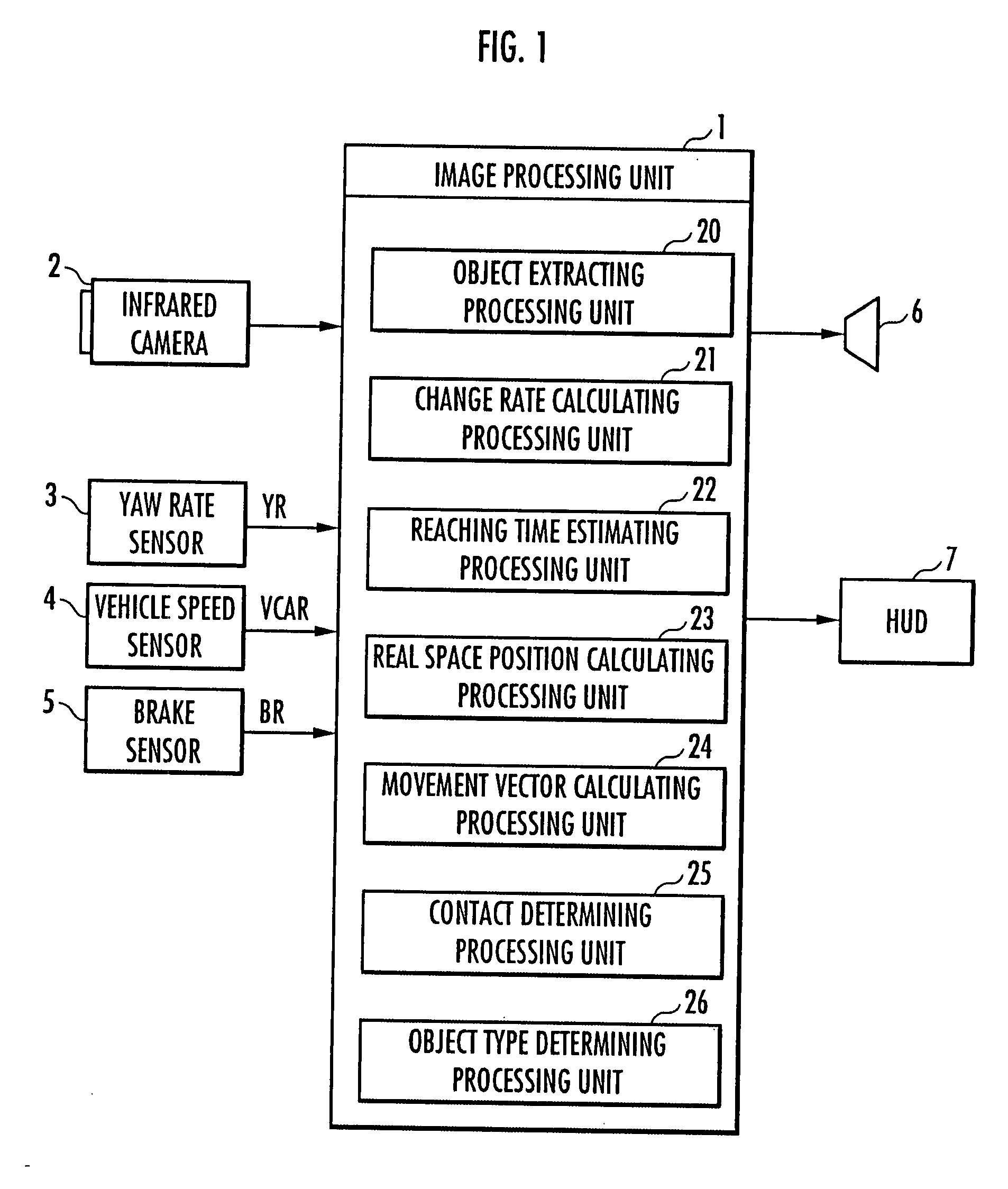
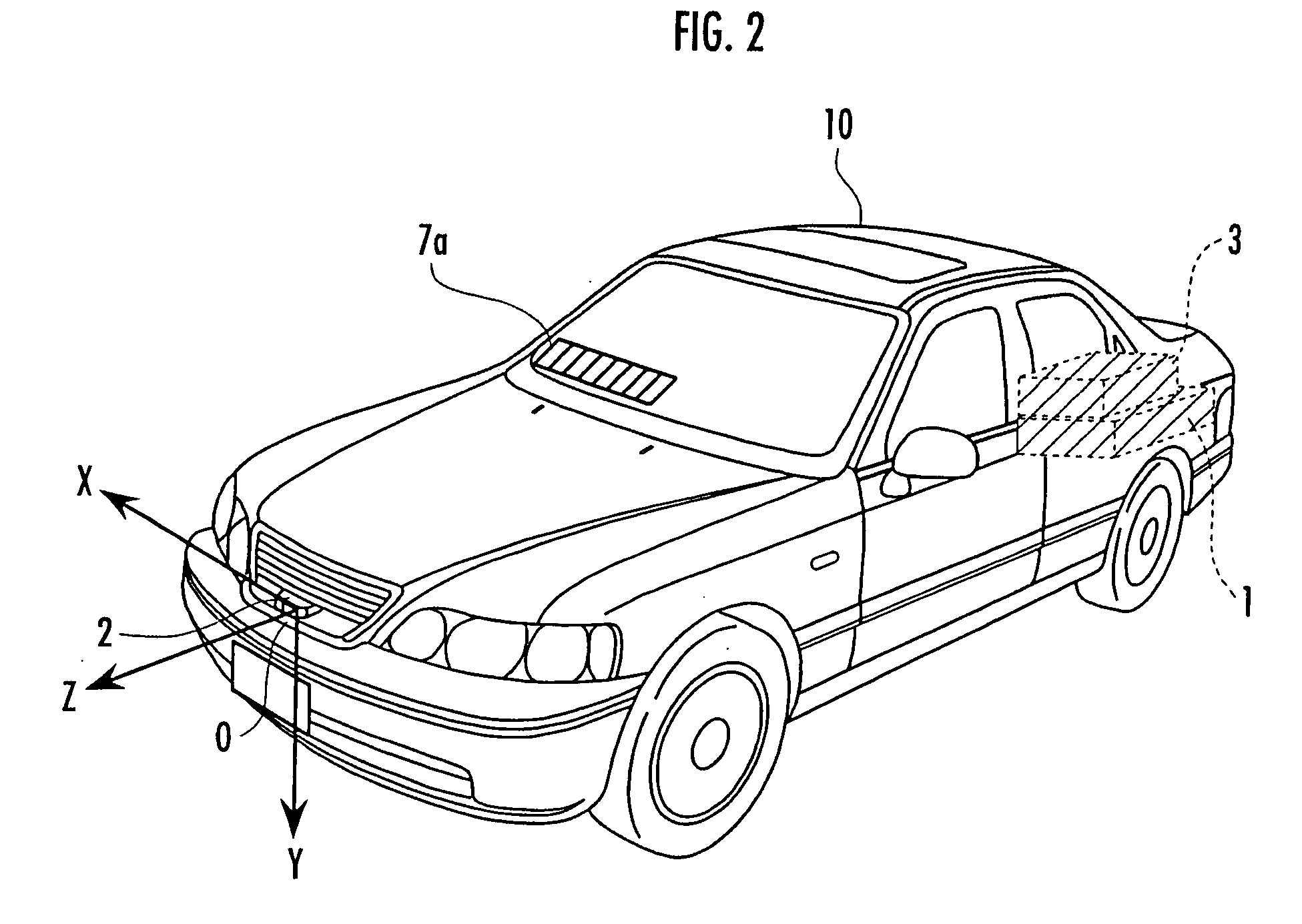
[0040]An embodiment of the present invention will now be described with reference to FIGS. 1-10.

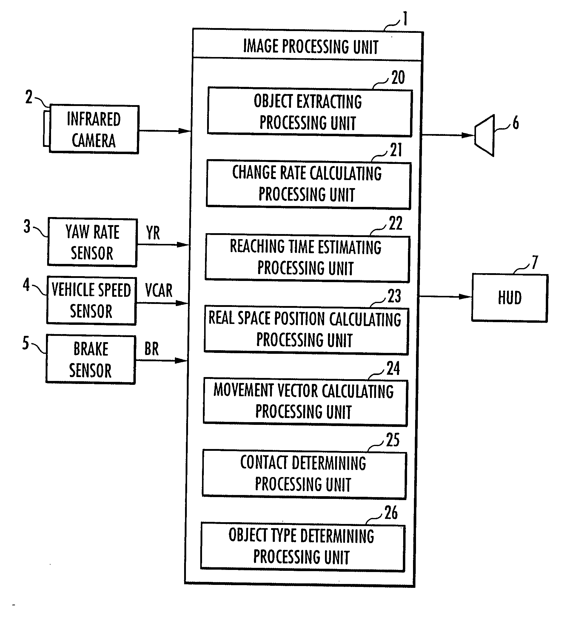
[0041]Referring to FIG. 1, a vehicle environment monitoring apparatus of the present invention includes: one infrared camera 2 (corresponding to the camera of the present invention) capable of detecting far-infrared rays; a yaw rate sensor 3 detecting the yaw rate of the vehicle; a vehicle speed sensor 4 detecting a traveling speed of the vehicle; a brake sensor 5 detecting an operation amount of a brake pedal by a driver; an image processing unit 1 detecting a monitored object (pedestrian or the like) in front of the vehicle based on an image obtained by the infrared camera 2 and outputting a warning when the monitored object would likely come into contact with the vehicle; a speaker 6 for generating the warning by sound; and a head up display (hereinafter, referred to as “HUD”) 7 for displaying the image obtained by the infrared camera 2 and also providing a display to cause the driver ...


PUM


Abstract

A vehicle environment monitoring apparatus capable of extracting an image of a monitored object in an environment around a vehicle by separating the same from the background image with a simple configuration having a single camera mounted on the vehicle is provided. The apparatus includes a first image portion extracting processing unit to extract first image portions (A1, A2) considered to be the head of a pedestrian from a currently picked up image and a previously picked up image by an infrared camera, a mask area setting processing unit to set mask areas (M1(0,0), M1(1,0), . . . , M1(5,8)) around the first image portion (A1) in the currently picked up image, and an object extracting processing unit to carry out pattern matching for the previously picked up image by a comparison pattern obtained through affine transformation of each mask area at a change rate (Rate) between the first image portions (A1, A2), and to set an area (Ar1) including the first image portion (A2) and a second image portion (M2(1,3), M2(2,3), . . . , M2(3,6)) where a displacement amount between the position (black point) corresponding to the centroid of the mask area and the matching position is smaller than a predetermined threshold value to be an image area of the monitored object.

Description

BACKGROUND OF THE INVENTION[0001]1. Field of the Invention[0002]The present invention relates to a vehicle environment monitoring apparatus, a vehicle environment monitoring program, and a vehicle environment monitoring method for monitoring an environment around a vehicle by detecting a monitored object existing in the environment around the vehicle from an image obtained by a camera mounted on the vehicle.[0003]2. Description of the Related Art[0004]There is conventionally proposed a vehicle environment monitoring apparatus that uses two cameras mounted on a vehicle to detect a distance between the vehicle and a monitored object according to the principle of trigonometrical survey, based on the displacement (parallax) of image portions of the same monitored object extracted from the images of the environment of the vehicle picked up by the respective cameras.[0005]There is also proposed a vehicle environment monitoring apparatus that extracts an image area of a monitored object by...

Claims


Application Information

Patent Timeline
Patent Type & Authority Applications(United States)
IPC IPC(8): G06K9/00
CPCG06T7/0002G06K9/00805G06T7/0026G06T7/32G06V20/58
Inventor NAGAOKA, NOBUHARUHASHIMOTO, HIDEKI
Owner ARRIVER SOFTWARE AB
Learn More