
Preform Base and Method of Making a Delamination and Crack Resistant Multilayer Container Base

a multi-layer container and container base technology, applied in the field of plastic base and method of making a delamination and crack resistant multi-layer container base, can solve the problems of stress whitening, lack of uniform standing surface, under-foot formation, etc., and achieve the effect of reducing the intrinsic viscosity of polyester polymer, and reducing the weight of the container bas

Inactive Publication Date: 2008-10-23
GRAHAM PACKAGING CO LP
View PDF21 Cites 60 Cited by
  • Summary
  • Abstract
  • Description
  • Claims
  • Application Information

AI Technical Summary

Benefits of technology

The patent describes a molded preform for blow molding a plastic container for pressurized applications. The preform has a base with a multilayer wall that includes a central thickened region, an intermediate region, and an outer region. The end cap region has a varying thickness profile to provide a reduction in weight compared to a spherical end cap profile. The end cap region includes a central thickened region, an intermediate region, and an outer region. The preform can be used to make a single-use plastic beverage container for pressurized liquids. The container has good resistance to delamination and cracking, and can be used for hot filling, cold filling, pasteurization, and retort.

Problems solved by technology

Two common problems are underformation of the feet, creating “rockers” which lack a uniform standing surface, and stress whitening, the creation of visual defects due to overstretching and / or cold stretching of the feet.
However, light-weighting has generally been accompanied by a reduction in base performance, such as increased creep and / or stress cracking.
However, pressurized multilayer containers often have a problem with layer delamination, either during pressurized filling, or later during storage and use.
Due to variations in thickness and orientation in different parts of the base, the base of a pressurized multilayer container is particularly susceptible to cracking, creep and delamination.

Method used


Image

  • Preform Base and Method of Making a Delamination and Crack Resistant Multilayer Container Base
  • Preform Base and Method of Making a Delamination and Crack Resistant Multilayer Container Base
  • Preform Base and Method of Making a Delamination and Crack Resistant Multilayer Container Base

Examples


Embodiment Construction

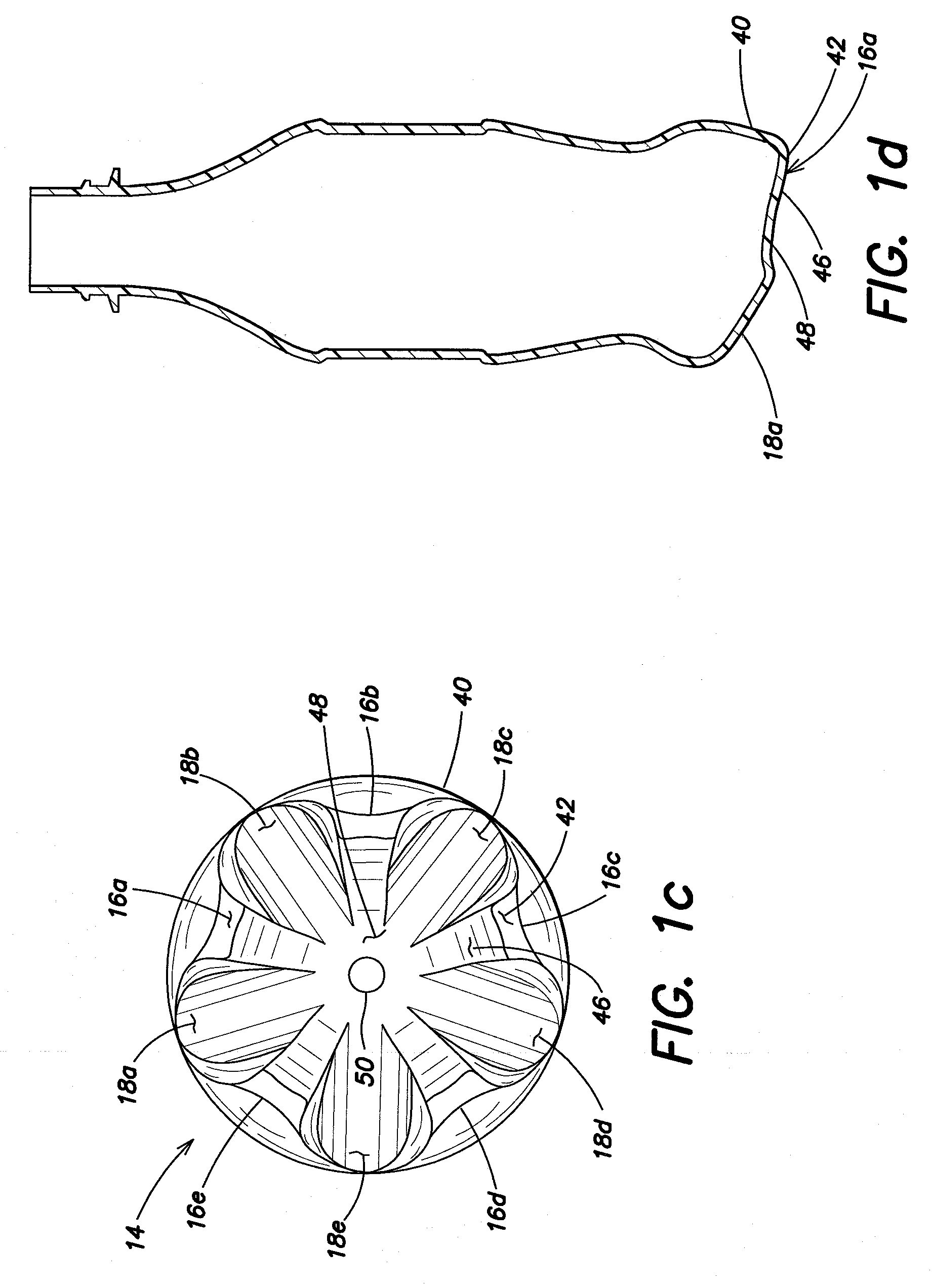
[0046]It is believed that when filling a carbonated soft drink container at for example, 4.2 volumes of CO2, the increase in pressure on the central dome creates a downward force which can result in downward movement of the dome. When the central dome moves down, this creates stress on the transition region between the central dome and foot pads. The present invention solves this problem by providing a preform base design having a non-spherical inner surface which produces a preform base thickness profile that results in less movement of the central dome and greater orientation in the transition region between the central dome and foot pad.

[0047]One embodiment of the invention will now be described for making a 250 milliliter (ml) carbonated soft drink (CSD) bottle having a multilayer sidewall and base. By utilizing a new preform design, a container is made that provides a desired level of crack and delamination resistance while reducing the material in the container base (lightweig...


PUM

PropertyMeasurementUnit
volumeaaaaaaaaaa
volumeaaaaaaaaaa
burst pressureaaaaaaaaaa

Abstract

Molded preform for blow molding a plastic container for pressurized applications, the preform having a base with a multilayer wall for forming a delamination and crack resistant multilayer footed container base. The preform base forming region has an end cap portion with a non-spherical inner wall, including a flattened central section joined by arcuate corner sections to a generally cylindrical outer section. The inner wall sections provide a varying end cap thickness profile which enhances orientation in select portions of the footed container base for improved performance and / or lightweighting of the container base.

Description

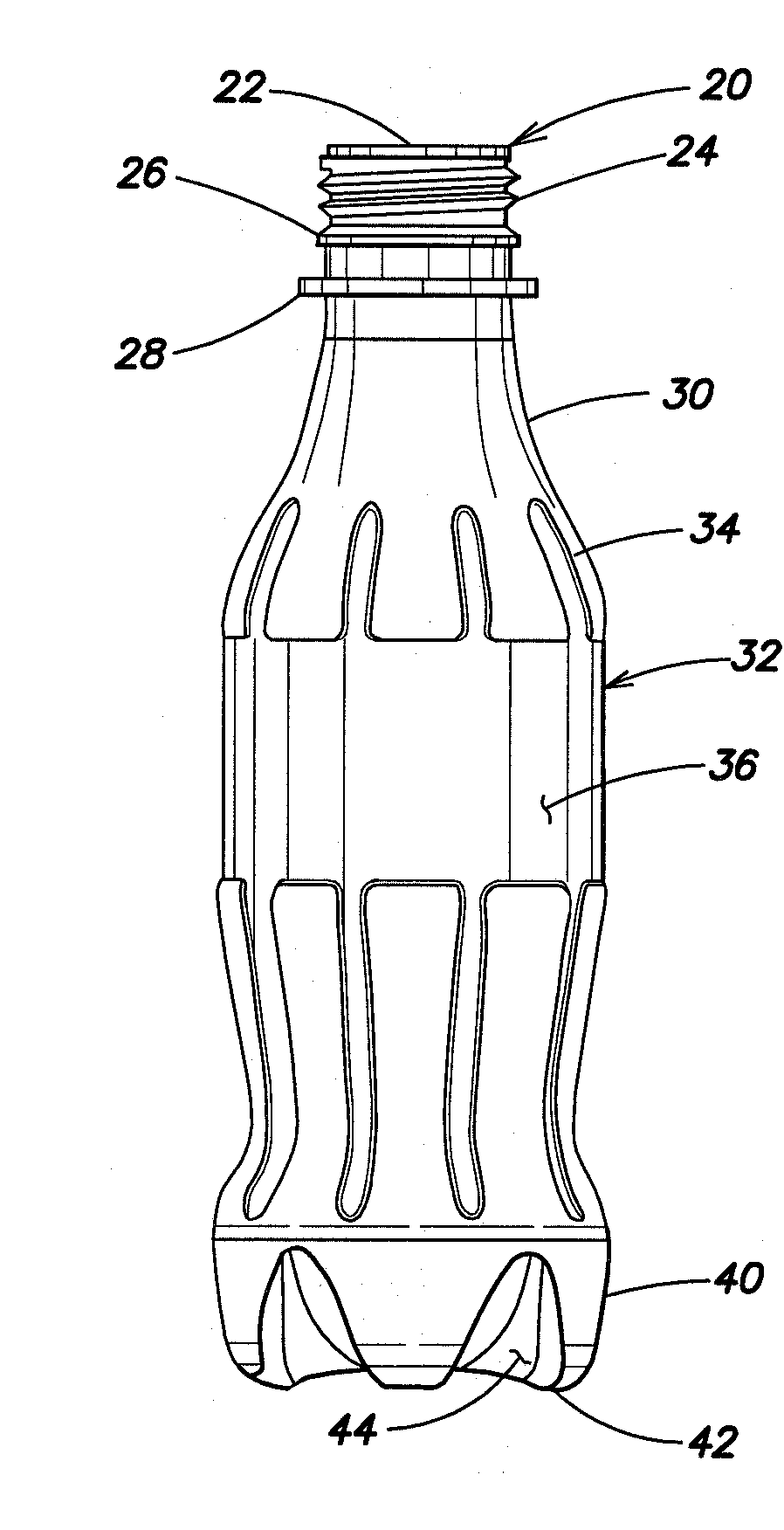
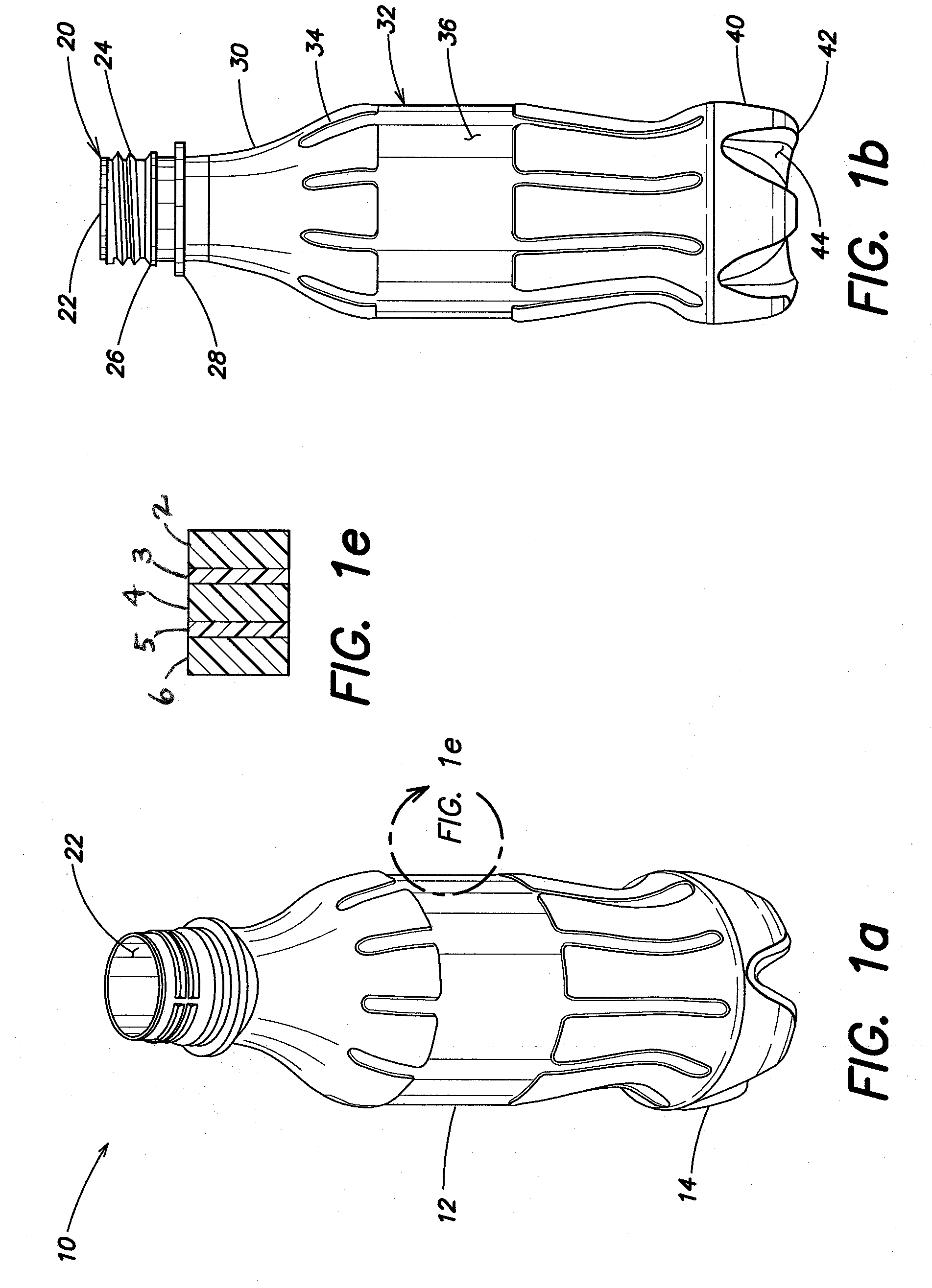
FIELD OF THE INVENTION[0001]This invention relates to pressurized plastic containers and to a preform and method enabling production of a lighter-weight multilayer footed container base having delamination and crack resistance.BACKGROUND OF THE INVENTION[0002]Transparent blow-molded polyester containers are the de facto standard for carbonated soft drinks (CSD), and are increasingly being used for other pressurized beverages (e.g., juice and beer). The polyester most commonly used, polyethylene terephthalate (PET), can provide superior clarity, pressurized strength, recyclability and ease of manufacture, at a competitive price.[0003]One of the most successful pressurized PET containers has a five-foot base design as described in Krishnakumar U.S. Pat. No. 4,785,949. The base includes a generally hemispherical bottom wall with five outwardly projecting feet symmetrically disposed about the circumference of the base. Following widespread adoption of the Krishnakumar 5-foot base, there...

Claims


Application Information

Patent Timeline
Patent Type & Authority Applications(United States)
IPC IPC(8): B65D90/02B32B1/00
CPCB29B11/08Y10T428/1352B29B11/14B29B2911/14053B29B2911/14066B29B2911/1408B29B2911/14093B29B2911/14113B29B2911/1412B29B2911/14126B29B2911/1414B29B2911/14146B29B2911/14153B29B2911/1422B29B2911/14226B29B2911/14233B29B2911/14326B29B2911/14333B29B2911/1444B29B2911/14466B29B2911/1464B29B2911/1498B29B2911/14986B29C49/06B29C49/12B29C49/221B29K2023/06B29K2023/086B29K2023/12B29K2027/06B29K2027/08B29K2033/20B29K2067/00B29K2067/006B29K2077/00B29K2995/0067B29B11/12B29C2949/3008B29C2949/3012B29C2949/3026B29C2949/302B29C2949/3016B29C2949/3028B29C2949/303B29C2949/3036B29C2949/3034B29C2949/3038B29C2949/3058B29C2949/3062B29C2949/306B29C2949/073B29C2949/0773B29C2949/072B29C2949/0777B29C2949/0818B29C2949/0872B29C49/0005B29C2949/3032B29C49/071B29C2949/0715B29C49/6605
Inventor PATEL, TAPAN Y.
Owner GRAHAM PACKAGING CO LP
Learn More