
NANO wire grid polarizer and liquid crystal display apparatus employing the same

a technology of liquid crystal display and wire grid, which is applied in the direction of nanooptics, nanotechnology, instruments, etc., can solve the problems of reducing light use efficiency, loss of light, and non-polarized light emitted from light sources, and achieve good light efficiency and contrast ratio, and large area

Inactive Publication Date: 2008-10-16
SAMSUNG ELECTRONICS CO LTD
View PDF13 Cites 28 Cited by
  • Summary
  • Abstract
  • Description
  • Claims
  • Application Information

AI Technical Summary

Benefits of technology

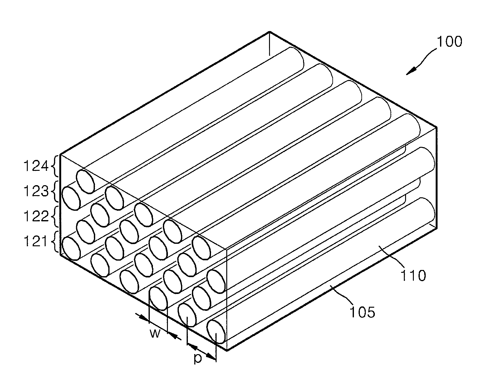
[0012]Exemplary embodiments of the present invention provide a nano wire polarizer using nano wires that can be manufactured to have a large area and can be mass-produced, and has good light efficiency and contrast ratio.
[0013]The present invention also provides a liquid crystal display apparatus that includes the nano wire polarizer to provide good light efficiency and contrast ratio, and improved production.

Problems solved by technology

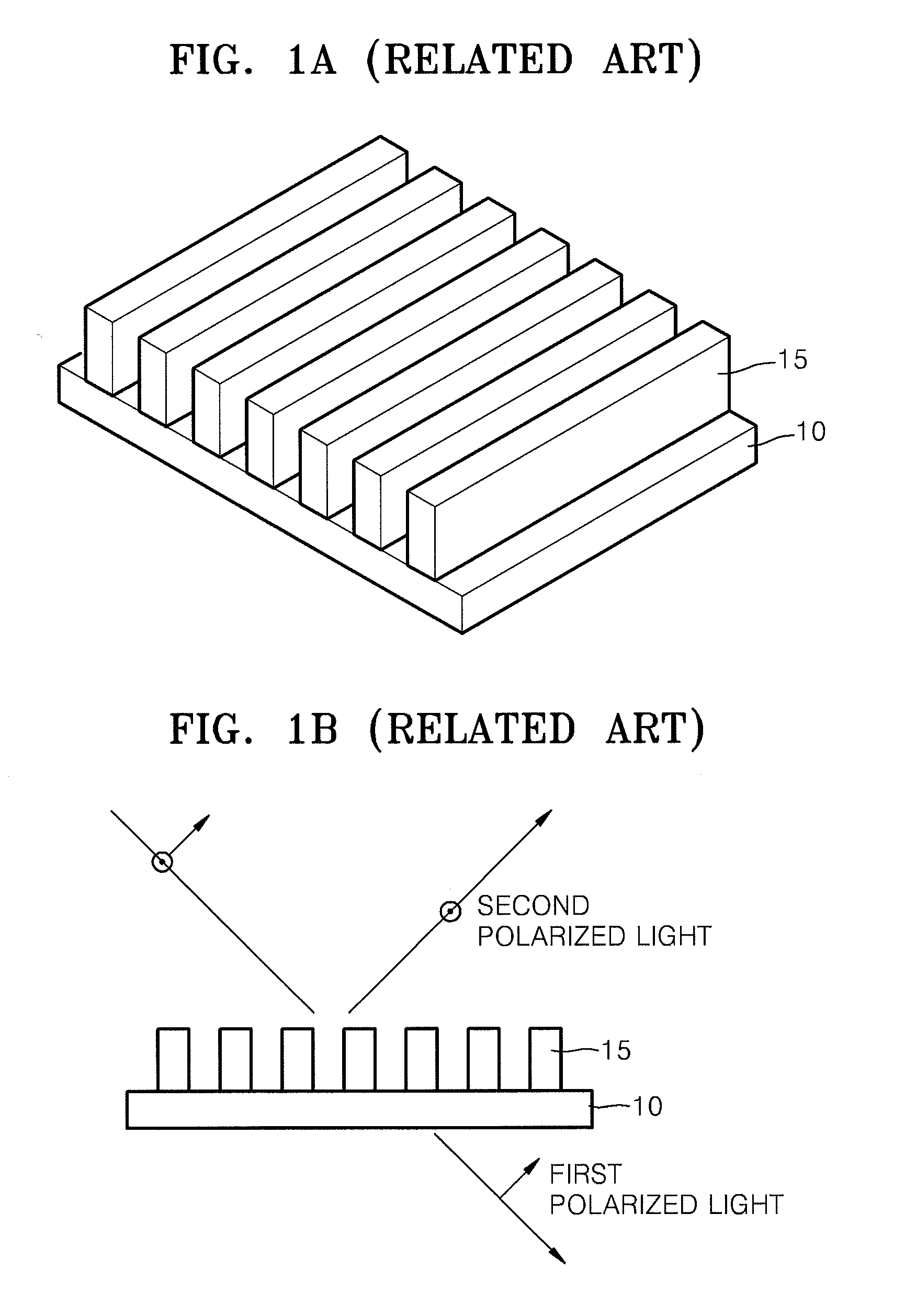
However, in general, light emitted from a light source is non-polarized light.
Accordingly, at least half of the light is lost, thereby reducing light use efficiency.
In addition, when some of the light to be transmitted is also absorbed, light loss is further increased.
However, since the maximum size of a WGP manufactured using such methods is 8 inches×8 inches, there is a problem in that it is difficult to mass produce such apparatuses having a large size.

Method used


Image

  • NANO wire grid polarizer and liquid crystal display apparatus employing the same
  • NANO wire grid polarizer and liquid crystal display apparatus employing the same
  • NANO wire grid polarizer and liquid crystal display apparatus employing the same

Examples


first example

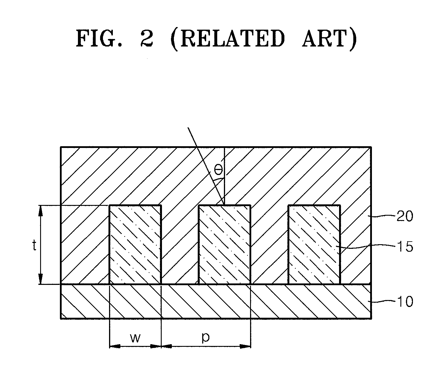
[0059]In the first example, L=3, p=50 nm and w / p=0.6. In addition, h=107 nm where h denotes a distance between the top of a core of the highest layer of a plurality of nano wire array layers and the bottom of a core of the lowermost layer of the nano wire array layers. FIGS. 8A and 8B are graphs respectively illustrating the Eff and the CR of the first example with respect to various wavelengths. When an angle of incident light θ is in the range of 0 to 60 degrees, the results of Eff>0.63 and CR>4000 can be obtained. The angle of incident light θ represents a slope of incident light with respect to a normal of the nano wire grid polarizer, as illustrated in FIG. 6.

second example

[0060]In the second example, L=4, p=60 nm, w / p=0.5 and h=186 nm. FIGS. 9A and 9B are graphs respectively illustrating Eff and CR of the second example. The results of Eff>0.64 and CR>18000 can be obtained with respect to an angle of incident light in the range of 0 to 60 degrees.

third example

[0061]In the third example, L=6, p=40 nm, w / p=0.5 and h=193 nm. FIGS. 10A and 10B are graph respectively illustrating Eff and CR of the third example. The results of Eff>0.65 and CR>58000 can be obtained with respect to an angle of incident in the range of 0 to 60 degrees.


PUM


Abstract

Provided are a nano wire grid polarizer and a liquid crystal display apparatus. The nano wire grid polarizer transmits light having a first polarization and reflects light having a second polarization. The polarizer includes a dielectric layer, and a plurality of nano wire array layers, each of the plurality of nano wire layers comprising a plurality of nano wires which are arranged in parallel to each other and spaced at regular intervals. The plurality of nano wire array layers are stacked to be spaced apart one another.

Description

CROSS-REFERENCE TO RELATED PATENT APPLICATION[0001]This application claims priority from Korean Patent Application No. 10-2007-0036621, filed on Apr. 13, 2007, in the Korean Intellectual Property Office, the disclosure of which is incorporated herein in its entirety by reference.BACKGROUND OF THE INVENTION[0002]1. Field of the Invention[0003]Apparatuses consistent with the present invention relate to a wire grid polarizer which transmits and reflects light according to polarization directions thereof, and more particularly, to a wire grid polarizer having nano wires that has good light efficiency and contrast ratio and can be manufactured to have a large area and can be mass-produced, and a liquid crystal display apparatus employing the wire grid polarizer.[0004]2. Description of the Related Art[0005]Polarization characteristics of light are used in many applications to conveniently control light emitted from light sources. For example, in the case of a liquid crystal display appara...

Claims


Application Information

Patent Timeline
IPC IPC(8): G02F1/1335G02B5/30
CPCB82Y20/00G02B5/3058G02F1/13362G02F2001/133548G02F2202/36G02F1/133548G02B5/30G02F1/1335B82Y30/00
Inventor KIM, GUK-HYUNLEE, SU-MI
Owner SAMSUNG ELECTRONICS CO LTD
Learn More