
Film detection device and method, and picture signal processing device and method

a technology of signal processing and detection device, which is applied in the direction of television system scanning details, standard conversion, television systems, etc., can solve the problems of low detection accuracy, degraded image quality, and 3:2 detection, and achieve the effect of high detection accuracy and quick respons

Inactive Publication Date: 2008-10-16
SONY CORP
View PDF18 Cites 9 Cited by
  • Summary
  • Abstract
  • Description
  • Claims
  • Application Information

AI Technical Summary

Benefits of technology

[0024]On the other hand, the scheme described in Patent Document 2 is advantageous in that it can detect not only both 3:2 and 2:2 pulldown but also edit points. However, the scheme has drawbacks. That is, the scheme is slow to detect the change of the input picture signal from a video material to telecine material. The scheme is less accurate than the scheme in Patent Document 1 in detecting 3:2 pulldown.
[0028]The scheme described in Patent Document 3 relies only on the local difference between field images for detection. On one hand, this provides two advantages, namely, quick response and capability to detect an arbitrary pulldown sequence which includes a hybrid material. On the other hand, the scheme has a drawback that erroneous detection is apt to occur for an image containing many vertical high frequency components. The scheme described in Patent Document 2 does not fail in film detection at least for an image locally containing many vertical high frequency components. Therefore, the scheme in Patent Document 3 is more prone to erroneous detection than that in Patent Document 2.
[0029]According to embodiments of the present invention, it is provided a film detection device and method which is capable of detecting a telecine material having an arbitrary pulldown sequence using a common circuit and which is also capable of handling picture edit points and hybrid materials thanks to high detection accuracy coupled with quick response. It is also another embodiment of the present invention to provide a picture signal processing device and method using the film detection device and method.
[0116]The embodiments of the present invention allows for detection of a telecine material having an arbitrary pulldown sequence using a common circuit.
[0117]Further, the embodiments of the present invention offer both high detection accuracy and quick response to additionally allow detection of a picture edit point and hybrid material.

Problems solved by technology

The scheme described in Patent Document 1 performs detection at intervals of five fields, resulting in slow detection.
If film detection is used for de-interlacing, slow detection is apt to lead to degraded image quality due to erroneous de-interlacing.
Moreover, this scheme is disadvantageous in that it can only detect 3:2 pulldown.
However, the scheme has drawbacks.
That is, the scheme is slow to detect the change of the input picture signal from a video material to telecine material.
Further, the detection accuracy for 3:2 pulldown is low because of the following reason.

Method used


Image

  • Film detection device and method, and picture signal processing device and method
  • Film detection device and method, and picture signal processing device and method
  • Film detection device and method, and picture signal processing device and method

Examples


first embodiment

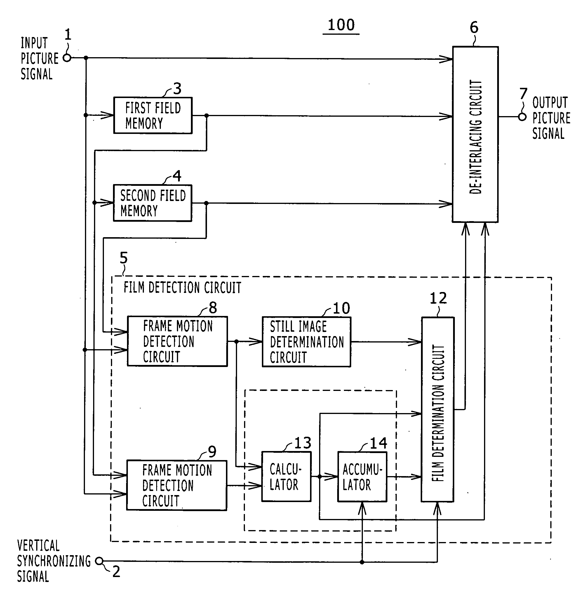
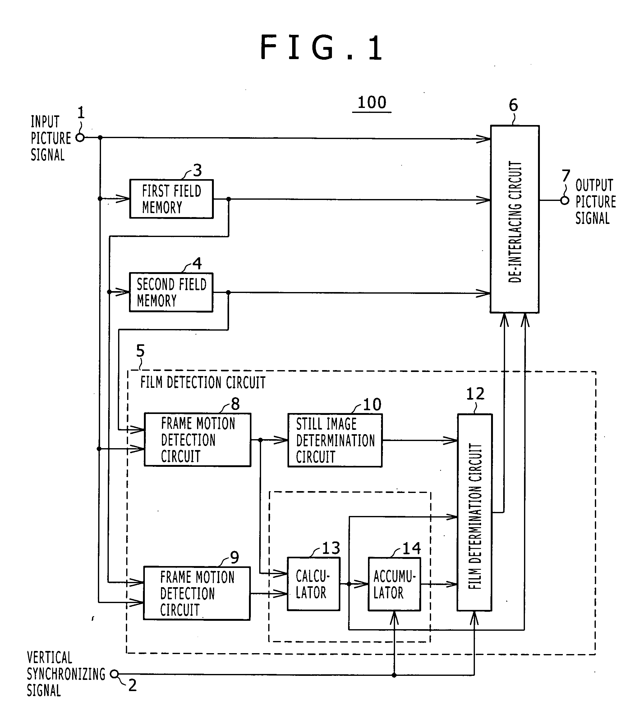
[0142]FIG. 1 is a view illustrating the overall configuration of a picture signal processing device according to a first embodiment of the present invention.

[0143]As illustrated in FIG. 1, a picture signal processing device 100 according to the first embodiment includes an input terminal 1 adapted to receive a picture signal, an input terminal 2 adapted to receive a vertical synchronizing signal, a first field memory 3 adapted to delay the picture signal received from the input terminal 1 by one field, a second field memory 4 adapted to delay the picture signal received from the input terminal 1 by two fields by delaying the picture signal already delayed one field by delaying one more field, a film detection circuit 5 adapted to determine the probability that the picture signal received from the input terminal 1 is an interlaced signal generated by the telecine process, a de-interlacing circuit 6 adapted to change de-interlacing methods according to the detection result of the film...

second embodiment

[0261]FIG. 16 is a view illustrating the overall configuration of the picture signal processing device according to a second embodiment of the present invention.

[0262]In FIG. 16, the components having the same function as those in the first embodiment are denoted by the same reference numerals, and a description thereof will be omitted.

[0263]A picture signal processing device 100A according to the second embodiment includes, a third field memory 27 adapted to delay a picture signal, which has been delayed by two fields, by one more field so as to delay the picture signal received from the input terminal 1 by three fields, a film detection circuit 28 adapted to determine whether the picture signal received from the input terminal 1 is an interlaced signal generated by the telecine process, and a de-interlacing circuit 29 adapted to change de-interlacing methods according to the detection result of the film detection circuit 28.

[0264]The de-interlacing circuit 29 according to the seco...

third embodiment

[0319]FIG. 20 is a view illustrating the overall configuration of the picture signal processing device according to a third embodiment of the present invention.

[0320]In FIG. 20, the components having the same function as those in the first and second embodiments are denoted by the same reference numerals, and a description thereof will be omitted.

[0321]A picture signal processing device 100B includes, a film detection circuit 44 adapted to determine whether the picture signal received from the input terminal 1 is an interlaced signal generated by the telecine process, and a de-interlacing circuit 45 adapted to change de-interlacing methods according to the detection result of the film detection circuit 44.

[0322]The dotted line in FIG. 20 represents the film detection circuit 44. The area enclosed by the dotted line illustrates the internal configuration of the same circuit 44. The frame motion detection circuit 30, first and second field motion detection circuits 31 and 32 and movin...


PUM


Abstract

Disclosed herein is a film detection device for determining whether an input picture signal is an interlaced signal generated by the telecine process, the film detection device including, a frame motion detection section, a field motion detection section, a motion judder detection section, and a film determination section.

Description

CROSS REFERENCES TO RELATED APPLICATIONS[0001]The present invention contains subject matter related to Japanese Patent Application JP 2007-107078 filed in the Japan Patent Office on Apr. 16, 2007, the entire contents of which being incorporated herein by reference.BACKGROUND OF THE INVENTION[0002]1. Field of the Invention[0003]The present invention relates to a film detection device and method for films having pictures recorded thereon, and to a picture signal processing device and method.[0004]2. Description of the Related Art[0005]The term “telecine process” refers to the process by which a picture recorded on a film such as movie film is converted into a television signal for broadcasting or other purposes. The telecine process normally converts the frame rate. At the same time, the telecine process splits each frame of the film into two fields because an interlaced signal is primarily used for broadcasting.[0006]The 2:2 pulldown and 3:2 pulldown techniques are popular as the tel...

Claims


Application Information

Patent Timeline
IPC IPC(8): H04N3/36
CPCH04N5/144H04N7/0115H04N7/012
Inventor SUZUKI, YOSHITO
Owner SONY CORP
Learn More