
Efficient driving tool for driving a screwing device

a screwing device and efficient technology, applied in the direction of screwdrivers, wrenches, manufacturing tools, etc., can solve the problems of ineffective transfer of force to the screw element, the ratchet ring or the screw element will be destroyed for a long time, and the force cannot be effectively transferred to the screw object, etc., to achieve the effect of increasing the efficiency of force transfer

Inactive Publication Date: 2008-10-16
HSIEH CHIH CHING
View PDF4 Cites 6 Cited by
  • Summary
  • Abstract
  • Description
  • Claims
  • Application Information

AI Technical Summary

Benefits of technology

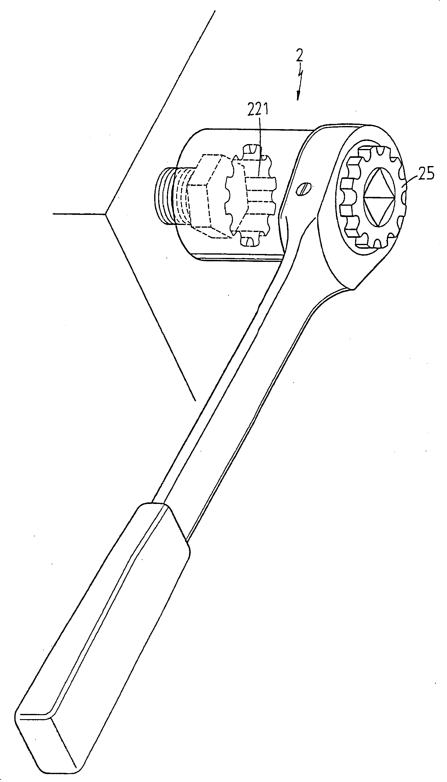
[0005]Accordingly, the primary object of the present invention is to provide an efficient driving tool for driving a screwing device, wherein the teeth in the screwing device is specially designed with a predetermined shape and a specific ratio so as to increment the efficiency of the transfer of force and protect the working tool from destroying, wearing and cracking.

Problems solved by technology

If the design of the teeth is not perfect, the force cannot be effectively transferred to the screw element and further the teeth of the ratchet ring or the screw element will be destroyed for a long time.
However, in the prior art way, the angles between different sections of the teeth and the recess are right angle and apex of angle will hurt the screw object and the contact is often point contact or the contact surface is not matched between the teeth of the ratchet ring and the contact surface of the screw object.
As a result, the force cannot be effectively transferred to the screw object.
Furthermore the right angle design in the ratchet ring makes the manufacturing process is tedious and inconvenient.

Method used


Image

  • Efficient driving tool for driving a screwing device
  • Efficient driving tool for driving a screwing device
  • Efficient driving tool for driving a screwing device

Examples


Embodiment Construction

[0015]In order that those skilled in the art can further understand the present invention, a description will be provided in the following in details. However, these descriptions and the appended drawings are only used to cause those skilled in the art to understand the objects, features, and characteristics of the present invention, but not to be used to confine the scope and spirit of the present invention defined in the appended claims.

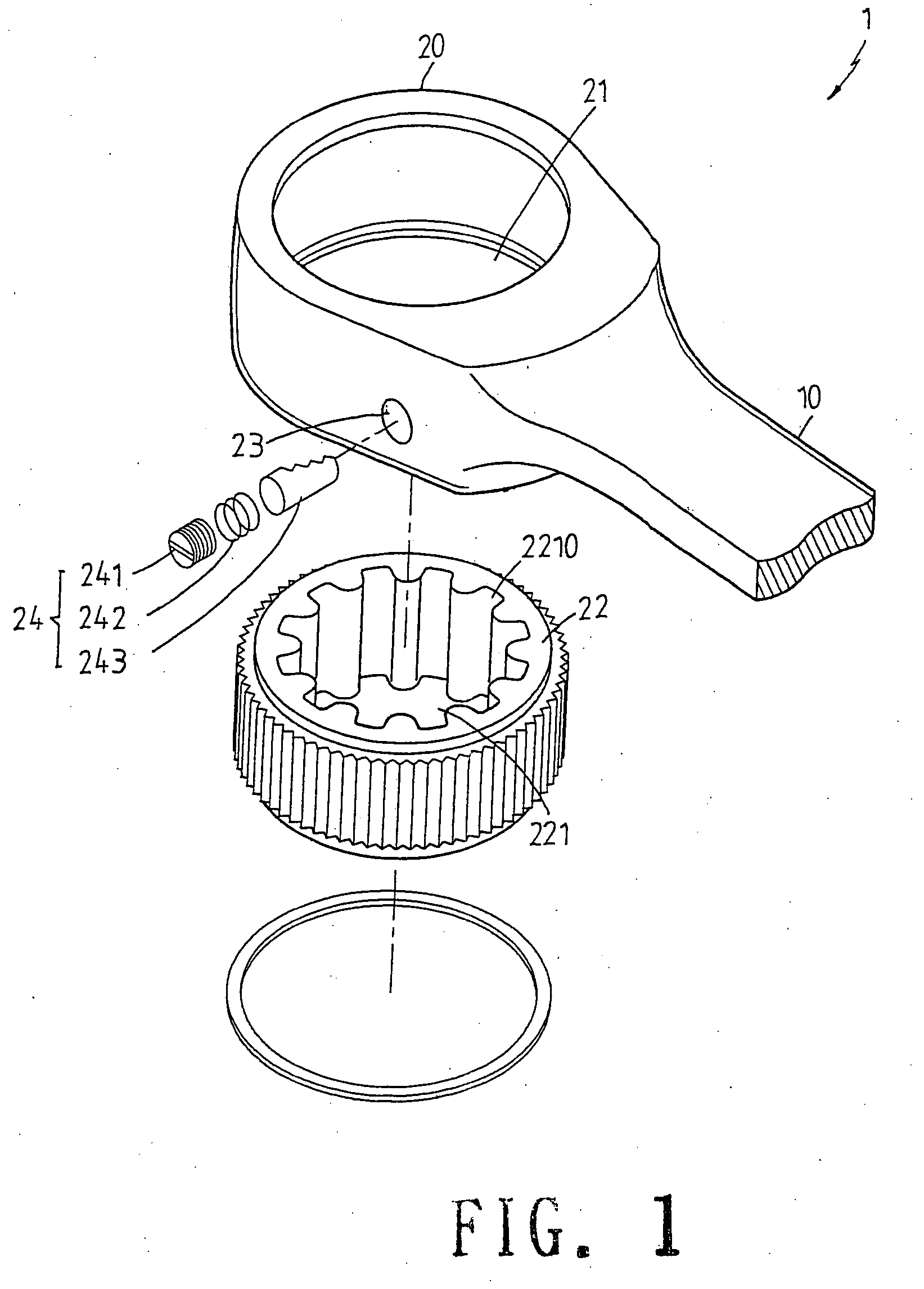
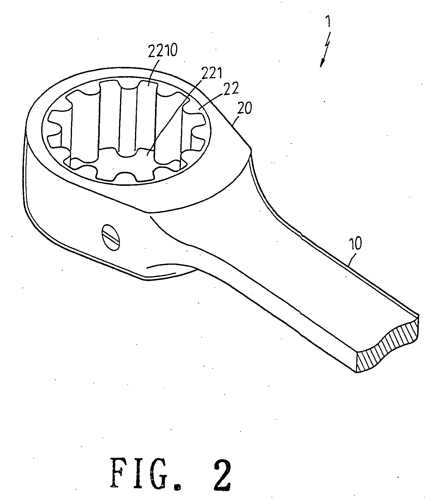
[0016]Referring to FIGS. 1 to 4, the structure of the present invention is illustrated. The present invention has the following elements:

[0017]A shank 10 is included.

[0018]A driving head 20 extends from the shank 10. The driving head 20 has a receiving hole 21 with a ratchet ring 22 received therein. One lateral side of the driving head 20 has a receiving groove 23.

[0019]A buckling unit 24 is received in the receiving groove 23. The buckling unit 24 has a positioning unit 241, an elastic unit 242 and a latch unit 243. By the positioning unit 241, t...


PUM


Abstract

A efficient driving tool for driving a screwing device, comprises: a driving head extending from the shank; the driving head having a receiving hole with a ratchet ring received therein; one lateral side of the driving head having a receiving groove. The ratchet ring has an engaging hole with a teeth set therein. A recess between two adjacent teeth is formed by two small arcs and one large arc; the large arc is at a bottom section of the recess and two small arcs are at tops of the recess. A straight section is between each small arc and the large arc; a section between two small arcs of two adjacent recesses is a transversal section which is a straight line. The screw device is one of a spanner and a socket.

Description

FIELD OF THE INVENTION[0001]The present invention relates to an efficient driving tool for driving a screwing device, wherein the teeth in the screwing device is special designed with a predetermined shape and a specific ratio so as to increment the efficiency of the transfer of force and protect the working tool from destroying, wearing and cracking.BACKGROUND OF THE INVENTION[0002]For a ratchet spanner, the teeth set in the spanner is used to contact with a screw element. All the forces of the spanner transferred to the screw element are transferred through the teeth in the ratchet ring of the spanner. Thus it is very important to design the shape or ratios of the different sections in the teeth so that the force can be transferred to the screw element effectively. If the design of the teeth is not perfect, the force cannot be effectively transferred to the screw element and further the teeth of the ratchet ring or the screw element will be destroyed for a long time. Thus there ar...

Claims


Application Information

Patent Timeline
Patent Type & Authority Applications(United States)
IPC IPC(8): B25B13/46
CPCB25B13/065B25B13/461
Inventor HSIEH, CHIH-CHING
Owner HSIEH CHIH CHING
Learn More