
Repair of Incompetent Heart Valves by Interstitial Implantation of Space Occupying Materials or Devices

a technology of space-occupying materials and heart valves, applied in the field of medical devices and methods, can solve the problems of reduced cardiac output, inadequate perfusion of tissues throughout the body, severe fatigue and shortness of breath, etc., and achieve the effect of modifying function

Inactive Publication Date: 2008-10-09
MEDTRONIC VASCULAR INC
View PDF15 Cites 8 Cited by
  • Summary
  • Abstract
  • Description
  • Claims
  • Application Information

AI Technical Summary

Benefits of technology

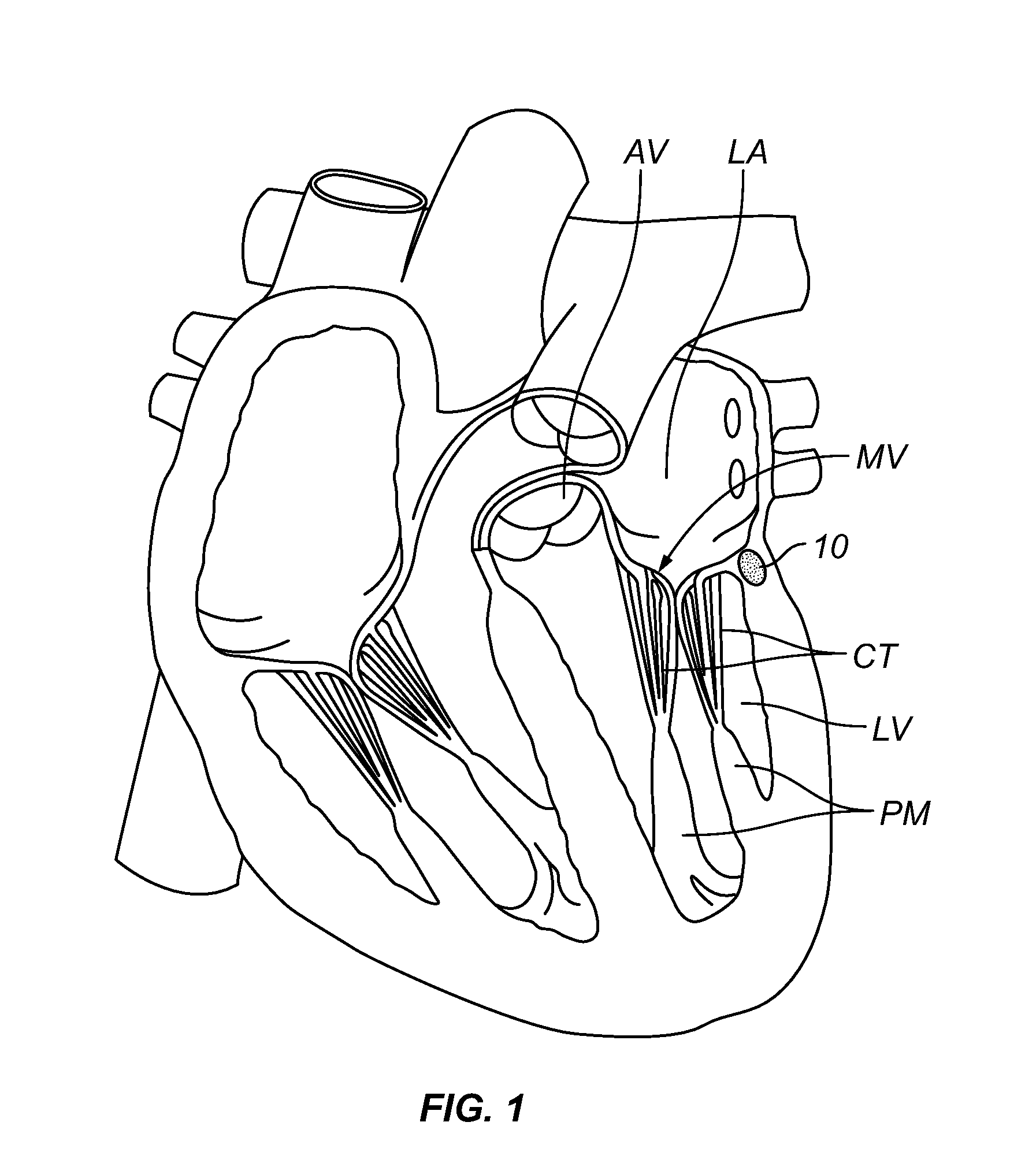
[0012]The present invention provides methods and systems for modifying the function of a cardiac valve by placing an interstitial space occupier (e.g., a substance or device) at one or more location(s) within heart tissue near the valve such that the space occupier will alter the shape and / or function of the valve in a manner that provides a therapeutic benefit. The interstitial space occupier may be placed within the myocardium adjacent to the annulus of the heart valve to be treated such that it does not reside within or protrude into the coronary sinus or any coronary blood vessel lumen and, thus, does not obstruct or disrupt normal coronary blood flow. Also, the methods and systems of the present invention do not require attachment of any apparatus to the annulus or leaflets of the cardiac valve being treated.
[0013]In accordance with the present invention, there is provided a method for improving the function of an incompetent cardiac valve that has leaflets, such method comprising the step of implanting a space occupier (e.g., a substance or device) at an interstitial location within heart tissue such that force exerted by the space occupier causes repositioning of at least one of the valve leaflets to improve competency of the valve. In some instances, the space occupier may be delivered to the desired interstitial location by a tissue penetrating catheter device that has a delivery cannula (e.g., a hollow needle) that is advanceable and retractable from the catheter. The tissue penetrating catheter is advanced transluminally to a position within the coronary vasculature (e.g., the coronary sinus, coronary artery or coronary vein) and the delivery cannula is then advanced from the catheter, through the wall of the sinus or blood vessel in which the catheter is positioned, and to an interstitial location near the incompetent cardiac valve. The space occupier is then delivered through the delivery cannula, causing the space occupier to be implanted at an interstitial location within heart tissue such that force exerted by the space occupier causes repositioning of at least one of the valve leaflets to improve competency of the valve. In some embodiments, the space occupier may comprise an injectable filler substance such as collagen, hyaluronic acid, polymeric materials, hydrogels, etc. In other cases, the space occupier may comprise one or more device(s) such as beads or an expandable member in the nature of a stent or expandable cage.

Problems solved by technology

However, irrespective of its underlying etiology, mitral regurgitation can result in decreased cardiac output and inadequate perfusion of tissues throughout the body, with various resultant symptoms, including severe fatigue and shortness of breath.

Method used


Image

  • Repair of Incompetent Heart Valves by Interstitial Implantation of Space Occupying Materials or Devices
  • Repair of Incompetent Heart Valves by Interstitial Implantation of Space Occupying Materials or Devices
  • Repair of Incompetent Heart Valves by Interstitial Implantation of Space Occupying Materials or Devices

Examples


example 1

Treatment of Mitral Valve Regurgitation by Injection of a Space Occupying Substance

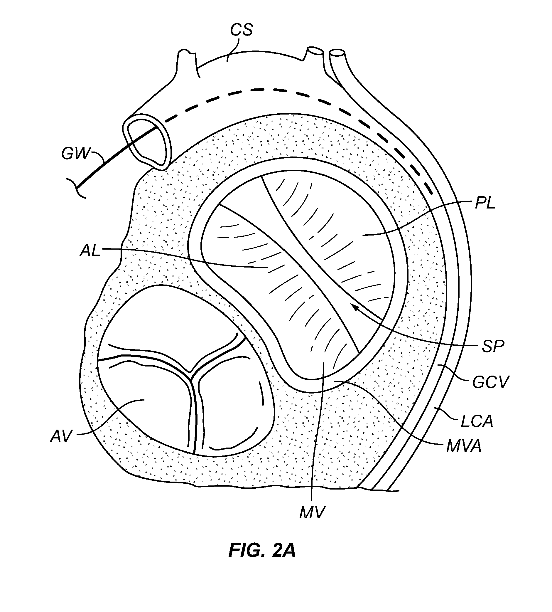
[0045]FIGS. 2A through 2F show steps in a method wherein the above described tissue penetrating catheter device 11 is used to inject a space occupying material at one or more interstitial location(s) within the heart near the mitral valve annulus MVA to cause the posterolateral leaflet PL of the mitral valve MV to move toward the anteromedial leaflet Al, thereby improving the closure of the leaflets and lessening regurgitation through the mitral valve MV.

[0046]As seen in FIG. 2A, a guidewire is initially advanced into the coronary sinus CS and, in some cases, may extend into a proximal portion of the great cardiac vein GCV, adjacent to the mitral valve MV. As shown, in this malfunctioning mitral valve MV, a space SP exists between the anteromedial leaflet AL and posterolateral leaflet PL during the systolic phase of the cardiac cycle, when a normally functioning mitral valve would be fully closed.

[004...

example 2

Treatment of Mitral Valve Regurgitation By Implantation of a Space Occupying Device

[0051]FIGS. 5A through 5F show steps in a method wherein the above described tissue penetrating catheter device 11 is used to implant a space occupying device 10b at one or more interstitial location(s) within the heart near the mitral valve annulus MVA to cause the posterolateral leaflet PL of the mitral valve MV to move toward the anteromedial leaflet Al, thereby improving closure of the leaflets and lessening regurgitation through the mitral valve MV.

[0052]As seen in FIG. 5A, a guidewire is initially advanced into the coronary sinus CS and, in some cases, may extend into a proximal portion of the great cardiac vein GCV, adjacent to the malfunctioning mitral valve MV. As shown, a space SP exists between the anteromedial leaflet AL and posterolateral leaflet PL of the valve during the systolic phase of the cardiac cycle, when a normally functioning mitral valve would be fully closed.

[0053]Thereafter,...


PUM

PropertyMeasurementUnit
Pressureaaaaaaaaaa
Flexibilityaaaaaaaaaa

Abstract

Incompetency or regurgitation of a cardiac valve is treated by injecting a space occupying material(s) or implanting a space occupying device(s) at an interstitial location adjacent to the valve such that the space occupying material or device exerts pressure on the valve causing one or more leaflets of the valve to be favorably repositioned. The procedure may be performed by open thoracotomy, thorascopically or transluminally using a tissue penetrating catheter.

Description

RELATED APPLICATIONS[0001]This application claims the benefit of U.S. Provisional Patent Application 60 / 910,767 filed Apr. 9, 2007.FIELD OF THE INVENTION[0002]The present invention relates generally to medical devices and methods, and more particularly to devices and methods for implanting space occupying materials or devices within cardiac tissue so as to exert pressure on the valve annulus thereby improving coaptation of the valve leaflets.BACKGROUND[0003]In humans and many mammals, the heart includes a number of chambers and valves of located between the chambers of the heart to control the flow of blood from chamber to chamber.[0004]For example, in humans, the mitral valve is located between the left atrium and left ventricle of the heart. The mitral valve consists of two leaflets (the anteromedial leaflet and the posterolateral leaflet) surrounded by a fibrous ring known as the mitral valve annulus. Two papillary muscles extend as finger-like projections from the wall of the le...

Claims


Application Information

Patent Timeline
IPC IPC(8): A61F2/24
CPCA61F2/2442A61F2/2451A61F2002/249A61F2210/0004
Inventor HUYNH, RANYLAMSON, THEODORE
Owner MEDTRONIC VASCULAR INC
Learn More