
Device for drawing lines on a sized sheet of paper and maintaining registration of the paper when it has been removed and is being replaced on the device

a technology for drawing lines and paper, applied in the field of devices, can solve the problems of inability to ensure the precise re-registration capability shown or suggested by phillips, the inability to conveniently or easily relocate the paper sheet precisely to the position, and the inability to return the paper sheet to the position without considerable difficulty, etc., and achieve the effect of heavier lines

Inactive Publication Date: 2008-10-02
SKETCH IT
View PDF13 Cites 8 Cited by
  • Summary
  • Abstract
  • Description
  • Claims
  • Application Information

AI Technical Summary

Benefits of technology

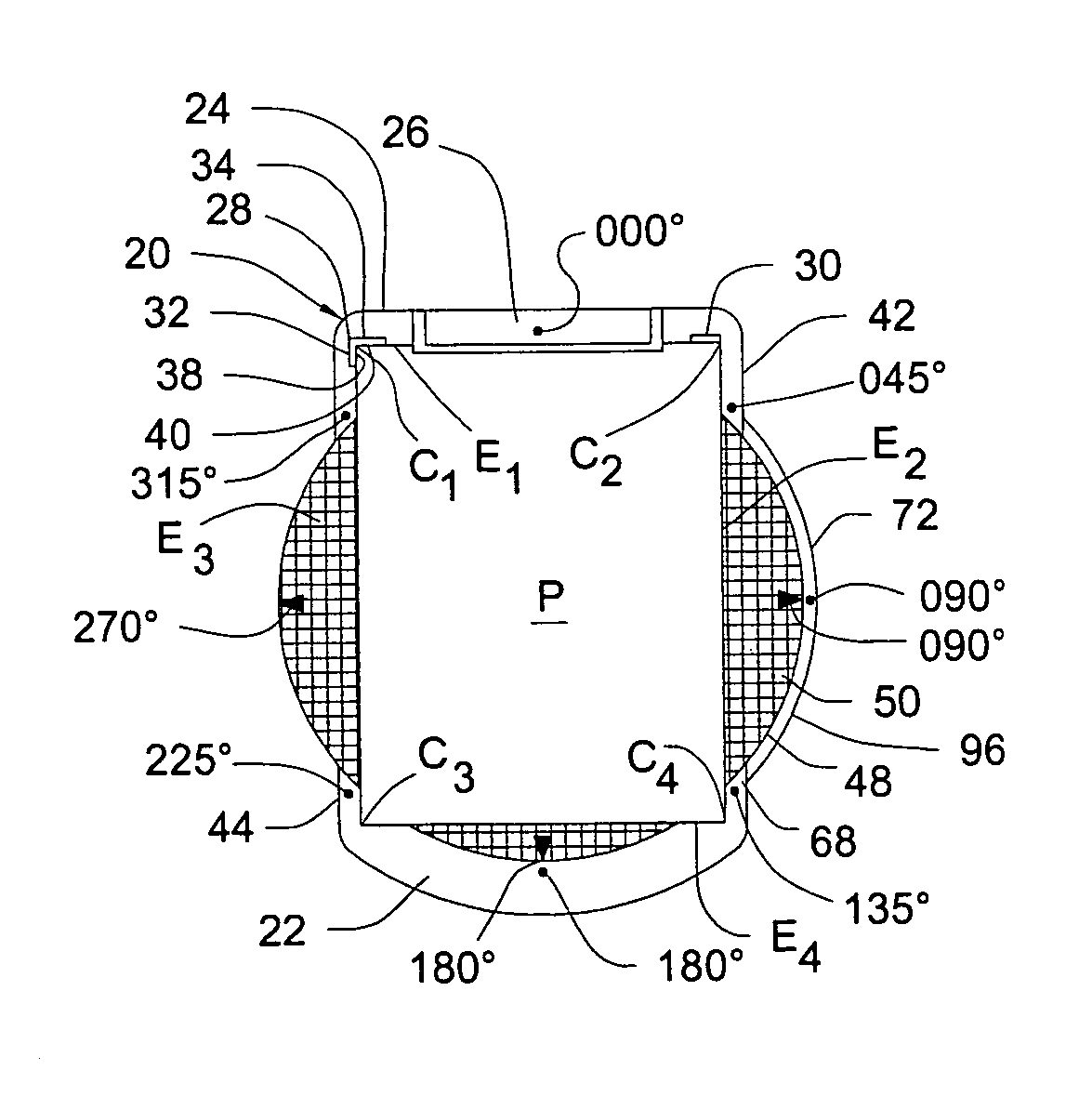
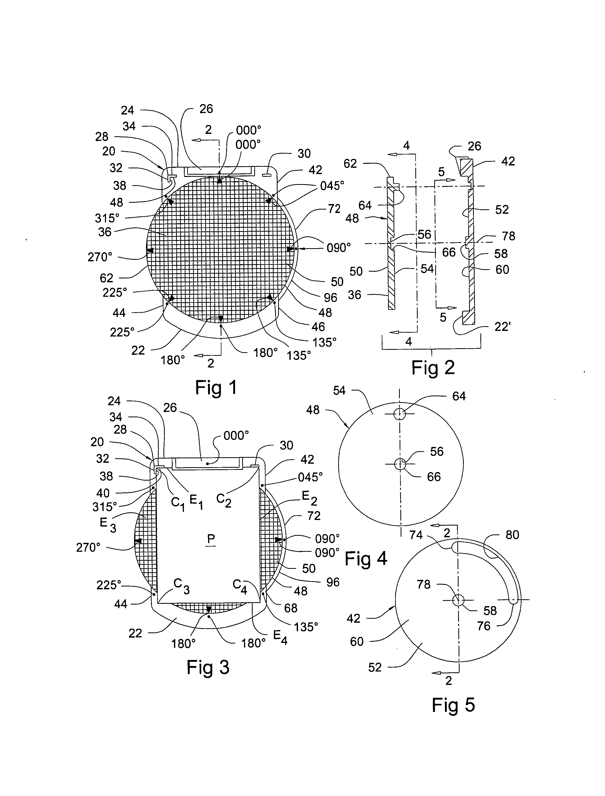
[0006]The registry position of a sheet of paper is set by having devices, herein referred to as registration marks, by preferably providing at least one L-shaped corner that establishes the precise position of a sheet of paper relative to the textured groove pattern sheet so that when the corner of a sheet of paper on which drawing is to be done is located in the L-shaped corner, it is also precisely positioned on the textured groove pattern sheet both horizontally and vertically. There can be additional registration marks when desired. These can be in the form of one or more straight registration marks setting the position of one or both sides and thus positioning the paper sheet even more positively horizontally. One or more additional straight registration marks may be located at the required location of the bottom of the paper sheet, or at the top, or both, relative to the textured groove pattern sheet for more precise registration of the paper sheet relative to the textured groove pattern sheet. Other L-shaped corner registration marks may be used to define the registration of the paper sheet precisely on the textured groove pattern sheet. Any suitable combination of such registration marks may be used within the purview of the invention. While the registration marks may be printed, painted or on an adhesively-backed label, or otherwise placed on the clipboard body. While they may be effectively flat and thus in the same plane as the plane of the part of the clipboard body where they are placed, it is preferable that the registration marks have a height extending upwardly from the plane of the part of the clipboard on which they are located that is just sufficient to accommodate paper sheets of several different thicknesses so that when thicker paper sheets are to be used for drawing thereon, they are able to be precisely positioned as described. The registration marks do not have to be as high as the full thickness of a thicker sheet in order to function properly and fully. The registration marks shown in the drawing are integrally made with the part of the clipboard main body on which they are located, by molding them with the molding of the clipboard main body. Alternatively, they may be made separately and then attached to the clipboard main body by any suitable attaching means, being very sure that they are precisely located so as to properly perform their functions.
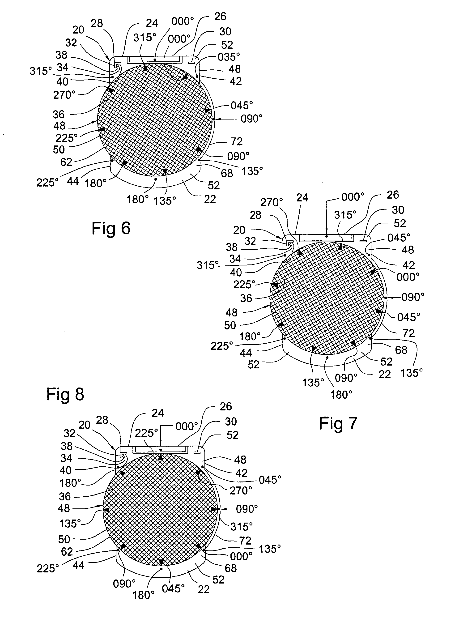
[0009]This arrangement has an additional advantage in that there may be a series of rotatable disc portions usable with the same clipboard fixed portion which have differently arranged textured groove pattern surfaces, thus allowing a broader scope of drawings using curves and other configurations such as that shown and disclosed in the earlier noted patent to Phillips, and also a series of different allowed arcuate movement ranges as earlier mentioned. Other variations in the textured groove pattern surfaces include a variation to provide certain grooves that are wider than the others, allowing for making some heavier lines to be drawn. Still others may be grooved to draw certain shapes. In some engineering and architectural sketches, these shapes may be those accepted for electrical and plumbing drawings, building shapes, and even some circles, ovals, and polygons that are in addition to the typical square, rectangular and triangular shapes. A sketcher may even use more than one of the available different textured groove pattern disc portions with the same sheet of sketch paper, and the paper sheet will still be precisely placed relative to the particular textured groove pattern being used. When a sketcher is in a very specific technical area of endeavor, custom textured groove patterns fitting the special needs for that particular work may be provided. There may also be different clipboard main bodies for different widths of the paper sheets, as well as different lengths of the paper sheets. Because the clip main body made for use in the United States of America that is usually made to accommodate paper sheets that are 8.5 inches wide and 11 inches long, or for other countries using the A6 sized paper sheets that are somewhat narrower but a little longer, that may be the most common use for the countries using those sizes of paper sheets. Other countries may use still different sized paper sheets, usually measured using the metric system. In those countries, the most-used size would be appropriate for regular production. Those for other sizes would likely be made on an as-required basis, because relatively few of them are likely to be required.

Problems solved by technology

There is a deficiency of the Phillips patent in that after the top of the textured paper on which some but not all of a sketch or drawing has been made and the paper sheet is then removed from that textured groove pattern surface, and thereafter there is an attempt made to replace the paper sheet over the textured surface, it cannot be conveniently or easily relocated precisely to the position it was in when earlier drawings had been made over it.
Returning the paper sheet to that position cannot be done without considerable difficulty, if it can even be done satisfactorily at all, because there are no accurate guides available for that purpose.
There is also an inherent problem with the structure shown in the Phillips patent when someone who needs to draw angled lines angled at any degree of angle other than those permitted by the textured groove pattern that is under the paper sheet.
Once that has been done, however, there is no assured precise re-registration capability shown or suggested by Phillips once the desired angled lines are earlier drawn, and the person doing the drawing desires to return the paper to its precise original registration to either add to the drawing or to rework the drawing at a later time and keep the additions or rework in proper registration relative to the textured groove pattern that was earlier used for drawing on the paper sheet.

Method used


Image

  • Device for drawing lines on a sized sheet of paper and maintaining registration of the paper when it has been removed and is being replaced on the device
  • Device for drawing lines on a sized sheet of paper and maintaining registration of the paper when it has been removed and is being replaced on the device
  • Device for drawing lines on a sized sheet of paper and maintaining registration of the paper when it has been removed and is being replaced on the device

Examples


Embodiment Construction

[0026]There are two groups of disclosure of the invention of a clipboard assembly. Each of these groups has variations of the details of the invention that are contained in the disclosures belonging to each of these groups. They may be referred to at times as a group including a turntable feature, and a group that does not include the turntable feature of the invention. Thus the group including the turntable feature builds on the other group and yet is all a part of the same invention that provides improvements over the Phillips patent.

[0027]Both groups of disclosure of the invention use the feature of the same registration marks on a clipboard that are an integral part of the broad invention, and both groups use the textured groove patterns of the prior U.S. Pat. No. 3,384,964, issued on May 28, 1968 to R. E. Phillips, and may use other patterns as well. Therefore, both groups use inventive improvements to the disclosure of that patent that constitute various features of the invent...


PUM


Abstract

Improvements in the instruments for drawing lines using grooves providing the presentation of lines that may be drawn by placing a sheet of paper over the presentation and engaging the sheet of paper with the point of a writing tool with sufficient force to press the engaged part of the paper into a selected groove and then moving the writing tool point within the line, depositing pencil lead or ink from the end of the writing tool on the paper that is pressed into the selected groove to form a line on the paper. The improvements include the provision of registration marks on a clipboard which has the presentation of grooves for lines to be drawn on the upper side of the clipboard, the registration marks acting as guidelines for the precise placement of the sheet of paper on which lines are to be drawn and its retention in that placement by a clip attached to the end of the clipboard and engaging the end of the sheet of paper for such retention. This precise placement of the sheet of paper allows a sheet of paper that has had one or more lines drawn on it in the manner noted above to be removed and later replaced on the clipboard in precisely the same location as it had when the line or lines were earlier drawn on it, with the result that any additional lines to be drawn will be in perfect relation to the lines earlier drawn, and the later drawings and the earlier drawings appear to have been made just as if the sheet of paper had not been removed between such drawings. Various shapes of such marks may be employed. Another major improvement is the provision of a turntable as a part of the upper surface of the clipboard, with the presentation of the array of grooves being in the upper surface of the turntable, and the turntable may be rotated under the sheet of paper to allow the drawing of lines at different angles to each other. The amount of rotation of the turntable is limited to a desired amount of arcuate movement, within ranges of 90°, 180°, 270°, or 360°. Another improvement is the ability to use different turntables having different types of arrays of grooves which are easily substituted as desired, not requiring completely different clipboard assemblies.

Description

[0001]This patent application is a continuation-in-part of U.S. patent application Ser. No. 11 / 508,767, filed on Aug. 23, 2006, by the same inventors as named herein. That application contains some improvements to the invention disclosed and claimed in the Phillips patent noted in the BACKGROUND, below.FIELD OF THE INVENTION[0002]Aids for drawing straight lines or various curvilinear lines that improve hand sketching and drawing by providing cleaner and more precise lines than is usually obtainable when one hand sketches on a typical sheet of paper. The aids include a textured groove pattern surface over which the sheet of paper is precisely placed. The aids also provide for the relocation of a sheet of paper over the textured groove pattern surface, after it has been removed with at least one line having been drawn on it, over the aid having the textured groove pattern surface for aiding a person to draw lines, so that is precisely realigned with that aid and the earlier-drawn line...

Claims


Application Information

Patent Timeline
IPC IPC(8): G09B11/04B43L3/00B43L13/24G09B11/00B43L13/02
CPCG09B11/04
Inventor HACHEY, DANIEL LOUISJOHNSON, RYAN LORON
Owner SKETCH IT
Learn More