
Adjustable hydraulic horizontal jack

a hydraulic horizontal jack and adjustable technology, applied in the field of adjustable hydraulic horizontal jacks, can solve the problems of limited function, constant lifting height and bearing capacity, and jacks that improve nothing except the height of the lowest position, and achieve the effect of wide application rang

Active Publication Date: 2011-03-17
CHANGSHU TONGRUN AUTO ACCESSORY
View PDF6 Cites 11 Cited by
  • Summary
  • Abstract
  • Description
  • Claims
  • Application Information

AI Technical Summary

Benefits of technology

The present invention is an adjustable hydraulic horizontal jack that has a simple structure and can be easily operated. It can change the height of the lowest position and the load by adjusting the length of the jib and link rods. This jack is suitable for use with both light and heavy automobiles, making it more versatile than other similar jacks.

Problems solved by technology

A drawback of the structure described above is: for the hydraulic horizontal lifting jacks with the same standards (i.e., the parameters such as oil pressure and stroke, etc. are constant), the lifting height and bearing capacity are constant because the lengths of jib and link rod can not be adjusted.
However, such a hydraulic horizontal jack improves nothing except increasing the height of the lowest position, and still has limited function.

Method used


Image

  • Adjustable hydraulic horizontal jack
  • Adjustable hydraulic horizontal jack

Examples


embodiment 1

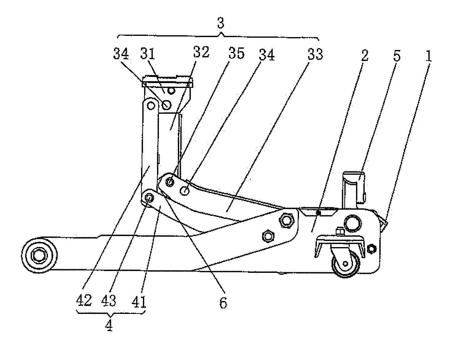
[0017]FIG. 1 shows a structure illustration according to a hydraulic horizontal jack of an embodiment of the present invention in lifting state, with a front arm 32 of a jib unit 3 and a second link rod 42 of the link rods 4 in a folded position.

[0018]Referring to FIG. 1, the hydraulic horizontal jack of the embodiment of the present invention includes the frame 2, the hydraulic unit 1, the jib unit 3, the link rods 4, a handle 5, and a connecting plate 6. The frame 2, the hydraulic unit 1, and the handle 5 are well-known in the art, and therefore will not be described further here. The technical feature of an embodiment of the present invention is the improvement of the jib unit 3 and link rods 4, wherein, the jib unit 3 includes a bracket 31, a front arm 32, a rear arm 33, a set pin 34, and a pin roll 35; the bracket 31 is hinged to one end of the front arm 32, the other end of the front arm 32 is hinged via the pin roll 35 to one end of the rear arm 33, and the other end of the r...

embodiment 2

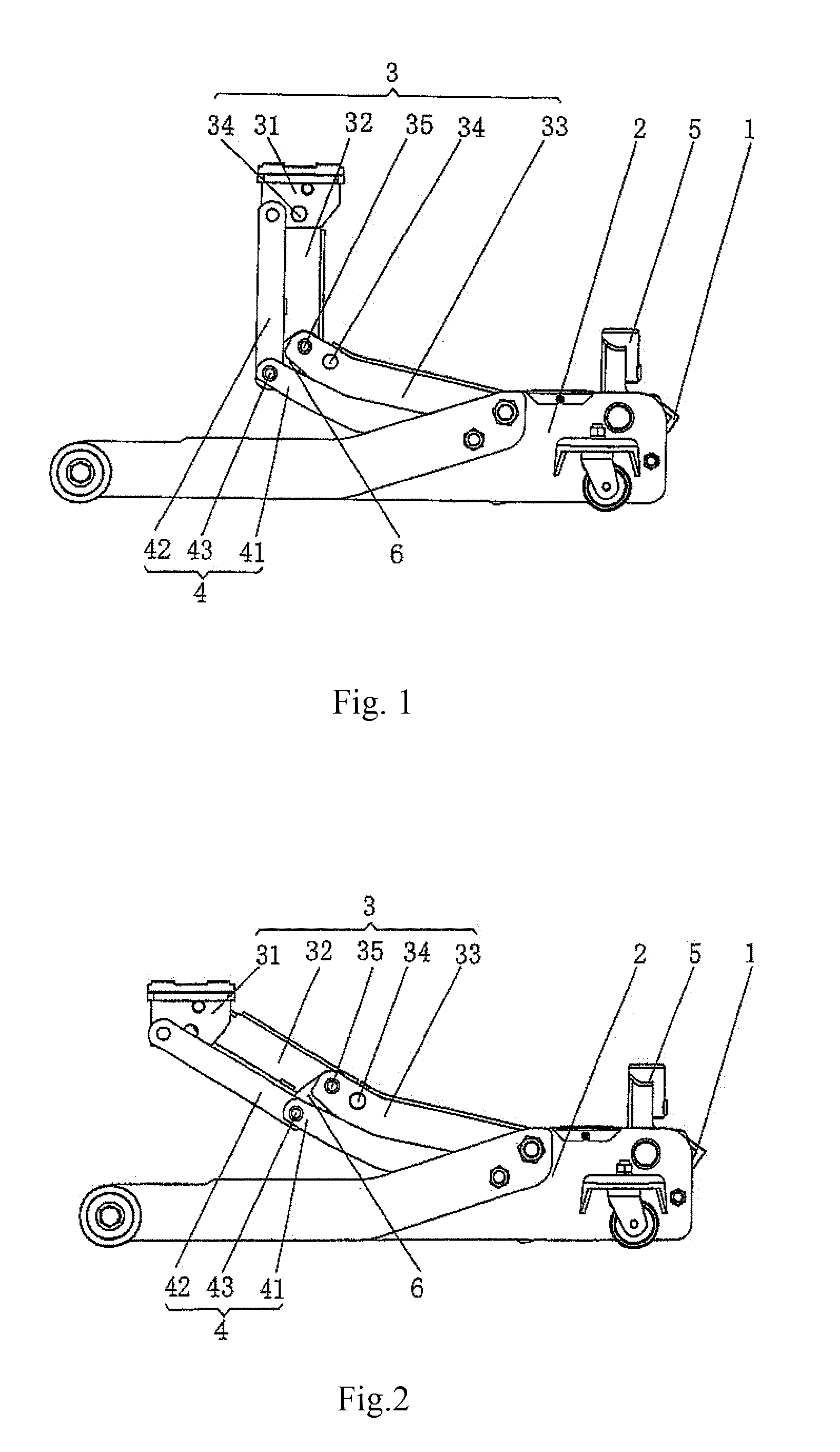
[0020]FIG. 2 shows a structure illustration according to an embodiment of the jack of the present invention in lifting state, with the jib and link rods in a normal position.

[0021]Referring to FIG. 2, the hydraulic horizontal jack of the embodiment of present invention includes a frame 2, a hydraulic unit 1, a jib unit 3, link rods 4, a handle 5, and a connecting plate 6. The frame 2, hydraulic unit 1, and handle 5 are well-known in prior art, and therefore will not be described further here. The technical feature of an embodiment of the present invention is the improvement of the jib unit 3 and link rods 4; wherein, the jib unit 3 includes a bracket 31, a front arm 32, a rear arm 33, a set pin 34, and a pin roll 35. The bracket 31 is hinged to one end of the front arm 32, the other end of the front arm 32 is hinged via the pin roll 35 to one end of the rear arm 33, and the other end of the rear arm 33 is pivotally attached to the frame 2; the set pin 34 is arranged between the fron...


PUM


Abstract

An adjustable hydraulic horizontal jack including a frame, a hydraulic unit, a jib unit, link rods, and a handle. Here, the structures of the jib and the link rod(s) are improved according to an embodiment. With the improved structures, the jack has rational structures and can act reliably. In addition, under the parameters equivalent to those of conventional hydraulic horizontal jacks, the jack of an embodiment of the present invention can change the height of the lowest position and the load by adjusting the length of the jib and link rods. Therefore, the jack is adapted to jacking up not only a light automobile with a low chassis but also a heavy automobile with a high chassis, thus having a wider scope of application.

Description

CROSS-REFERENCE TO RELATED APPLICATION(S)[0001]This application claims priority to and the benefit of Chinese Patent Application Number 200910182545.8, filed in the State Intellectual Property Office (SIPO) of China on Sep. 16, 2009, the entire content of which is incorporated herein by reference.FIELD OF THE INVENTION[0002]The present invention relates to lifting apparatus, and more particularly, to an adjustable hydraulic horizontal jack with improvements to structures of a jib and link rods of the hydraulic horizontal jack.BACKGROUND OF THE INVENTION[0003]At present, the common hydraulic horizontal jacks in the market mainly include a frame, a hydraulic unit, a jib unit, a link rod, and a handle, wherein, the jib unit includes a jib and a bracket arranged on the jib; one end of the link rod is pivotally attached to the frame, and the other end of the link rod is hinged to the bracket of the jib unit. When a heavy object is to be lifted, the handle can be pressed repeatedly, so th...

Claims


Application Information

Patent Timeline
Patent Type & Authority Applications(United States)
IPC IPC(8): B66F3/25B66F3/24B66F5/04
CPCB66F5/04B66F3/24
Inventor SHEN, MINCHEN, JIANGWANG, JINGFANG
Owner CHANGSHU TONGRUN AUTO ACCESSORY
Learn More