
Aligning Timebases to Share Synchronized Periodic Signals

a timebase and periodic signal technology, applied in the direction of digital transmission, multiplex communication, instruments, etc., can solve the problem of no longer agreeing on the edge, achieve the effect of facilitating the resolution of the edge of the reference signal, superior results, and facilitate multiple devices

Active Publication Date: 2008-10-02
NATIONAL INSTRUMENTS
View PDF24 Cites 71 Cited by
  • Summary
  • Abstract
  • Description
  • Claims
  • Application Information

AI Technical Summary

Benefits of technology

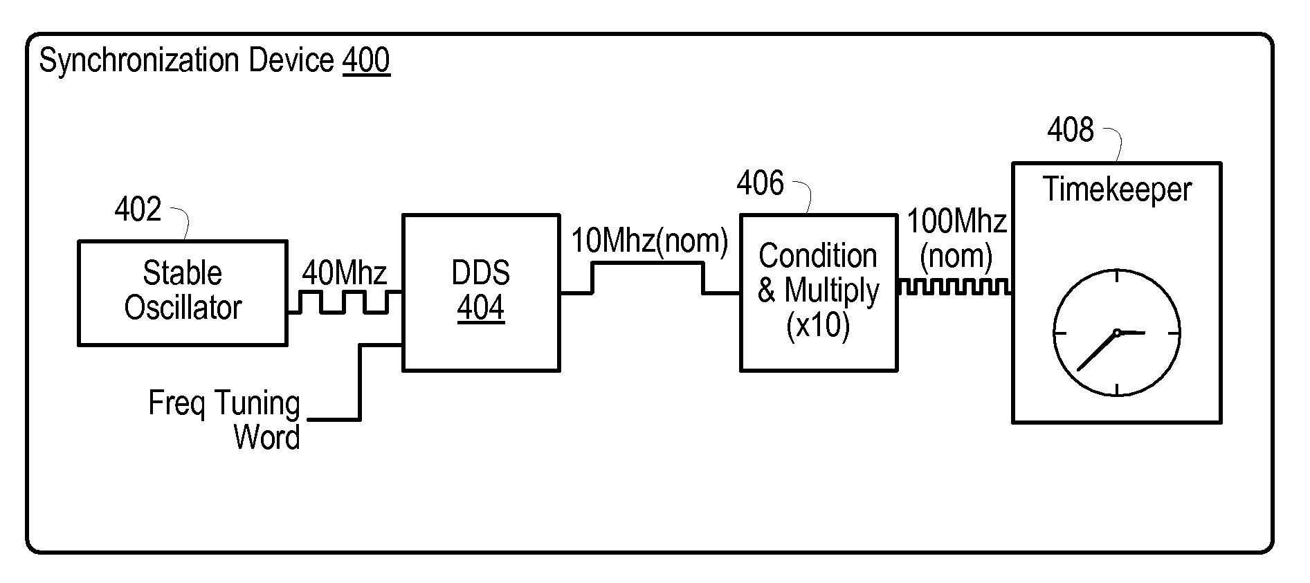
[0013]Various embodiments of the present invention provide a system and method for aligning a local timebase to a remote timebase given a timebase error value from a higher-level protocol, and using the aligned timebases to generate and distribute synchronized events and synchronized adjustable frequency periodic signals across a domain using the aligned timebases. In one set of embodiments, these same events and periodic signals may be generated with even tighter synchronization than what may be provided by the aligned timebases. Slightly speeding up or slowing down a periodic signal used to count time, a local timebase may be aligned to a remote timebase when given an error value from a higher-level protocol. A Direct Digital Synthesizer (DDS) or Numerical Controlled Oscillator (NCO) may be used to finely adjust the frequency of its output signal. This signal, or a derivative, may then be used to clock circuitry that keeps count of time, herein referred to as a timekeeper. By correlating the error signal to a new frequency, time may be made up or lost in a smooth manner.
[0015]In another set of embodiments, a common reference periodic signal may be shared between all devices. The reference signal may be physically wired to all devices or it may be a wireless connection such as a GPS pulse-per-second signal. Once the devices are synchronized via a synchronization protocol and an alignment mechanism, their common timebase may be used to identify a particular edge or period of the common reference periodic signal that may occur at a future time. Devices may then synchronize their activities or generate synchronized periodic signals by starting the activity or periodic signal at a time when the agreed upon edge or period of the reference periodic signal arrives. Tight enough synchronization provided by the protocol may facilitate resolving a reference signal edge, leading to superior results, while in some applications it may be adequate to resolve a particular period of a reference signal. Care may need to be taken that the agreed upon reference signal edge is not too far ahead in time, otherwise a drift of the Master timekeeper from the reference periodic signal may cause the edge to be no longer agreed upon. Possible ways to address this issue may include operating the Master timekeeper to run its timekeeper off of the periodic reference signal, or setting the future time closer to the current time to eliminate drift and / or minimize drift, respectively.
[0017]If the distributed reference clock is of a sufficiently low frequency, the higher-level protocol may be able to resolve time to a tighter resolution than the period of a reference clock. For example, if the higher-level protocol is capable of resolving time down to 20 ns, and the period of the reference clock is 100 ns, then the synchronization of the system may be subject to the skew of the reference clock. If the skew of the reference clock is 50 ns between two devices, the higher-level protocol may be able to detect the skew, but additional circuitry may be needed to also correct the skew. One possible solution may be to provide a PLL (phase locked loop) capable of adjusting the phase of an output periodic signal according to instructions from the timekeeper. Thus, the high-level protocol may be able to align the PLL outputs of two devices to within its resolution, in this example, 20 ns. Because the reference clock is distributed, the high-level protocol may not need to continue re-evaluating and re-synchronizing the system.

Problems solved by technology

Care may need to be taken that the agreed upon reference signal edge is not too far ahead in time, otherwise a drift of the Master timekeeper from the reference periodic signal may cause the edge to be no longer agreed upon.

Method used


Image

  • Aligning Timebases to Share Synchronized Periodic Signals
  • Aligning Timebases to Share Synchronized Periodic Signals
  • Aligning Timebases to Share Synchronized Periodic Signals

Examples


Embodiment Construction

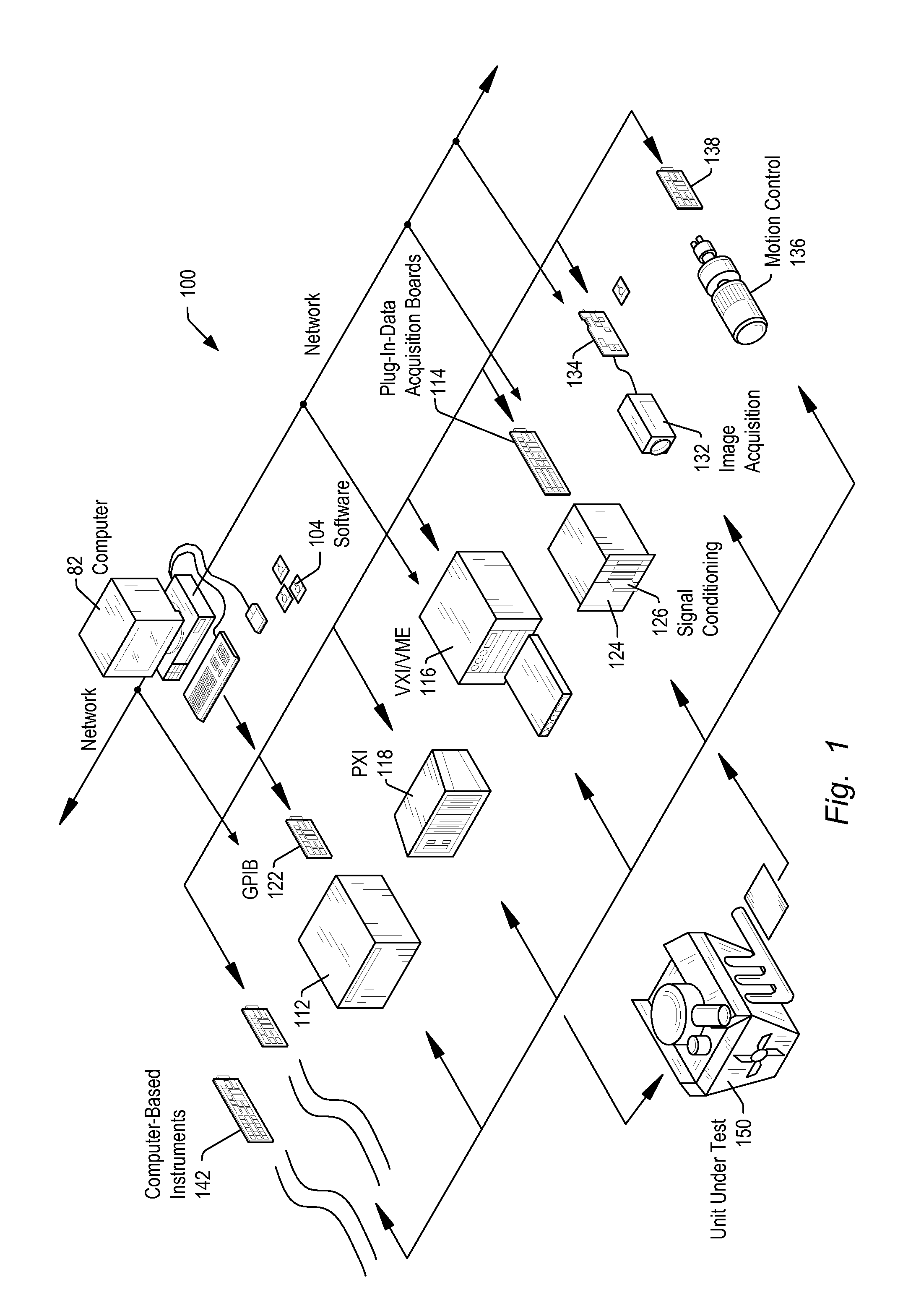
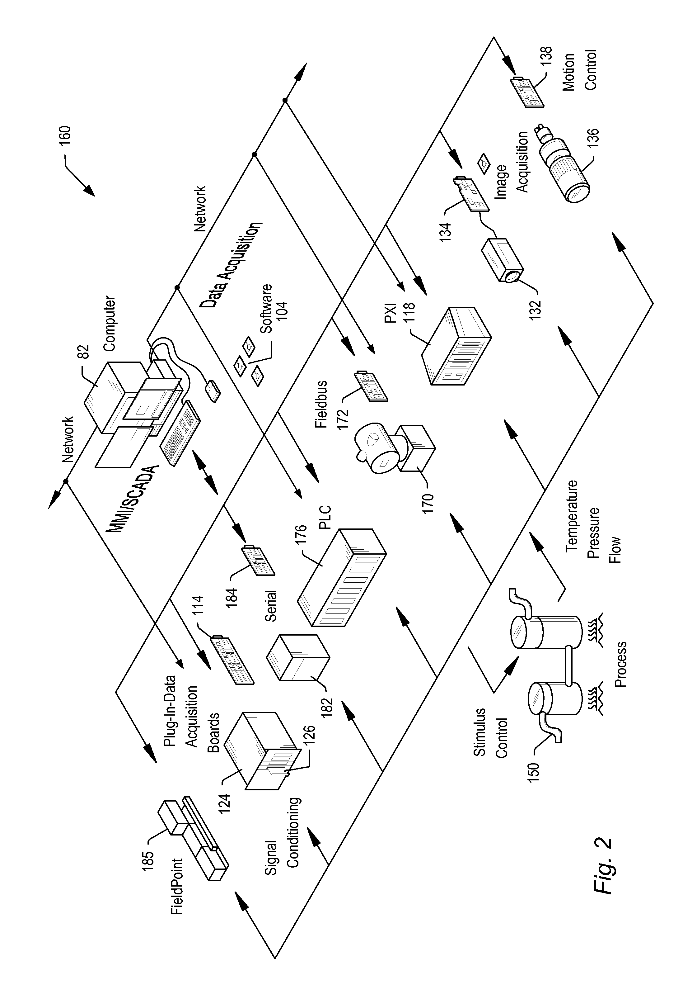
[0028]Embodiments of the present invention may be used in systems configured to perform test and / or measurement functions, to control and / or model instrumentation or industrial automation hardware, or to model and simulate functions, e.g., modeling or simulating a device or product being developed or tested, etc. However, it is noted that the present invention may equally be used for a variety of applications, and is not limited to the applications enumerated above. In other words, applications discussed in the present description are exemplary only, and the present invention may be used in any of various types of systems. Thus, the system and method of the present invention is operable to be used in any of various types of applications, including the control of other types of devices such as multimedia devices, video devices, audio devices, telephony devices, Internet devices, etc.

[0029]FIG. 1 illustrates an exemplary instrumentation control system 100 which may be configured accor...


PUM


Abstract

A system and method for aligning a local timebase to a remote timebase given a timebase error value from a higher-level protocol, and using the aligned timebases to generate and distribute synchronized events and synchronized adjustable frequency periodic signals across a domain using the aligned timebases. Slightly speeding up or slowing down a periodic signal used to count time, a local timebase may be aligned to a remote timebase when given an error value from a higher-level protocol. A device may be configured to begin generating a periodic waveform at an agreed upon time in the future, once the timebases are aligned, where the time may be synchronized to remote devices via a synchronization protocol and an alignment mechanism. Remote periodic signals may remain synchronized to each other as long as the higher-level protocol and timebase alignment algorithm keep the timebases aligned. A common reference periodic signal may be shared between all devices, and the reference periodic signal or a conditioned version of the reference periodic signal may be specified as the periodic signal to control the operation of the timebase circuitry. The common reference periodic signal may improve synchronization performance beyond the capabilities of the higher-level protocol, and may in addition provide means for synchronization fault tolerance.

Description

FIELD OF THE INVENTION[0001]The present invention relates to the field of periodic signal distribution and synchronization in measurement and / or control systems, and more particularly to a system and method for aligning timebases to share synchronized periodic signals.DESCRIPTION OF THE RELATED ART[0002]In many industrial applications (and others), instruments collect data or information from an environment or unit under test (UUT), and may also analyze and process acquired data. Some instruments provide test stimuli to a UUT. Examples of instruments include oscilloscopes, digital multimeters, pressure sensors, arbitrary waveform generators, digital waveform generators, etc. The information that may be collected by respective instruments includes information describing voltage, resistance, distance, velocity, pressure, oscillation frequency, humidity, and / or temperature, among others. Computer-based instrumentation systems typically include transducers for capturing a physical pheno...

Claims


Application Information

Patent Timeline
IPC IPC(8): H04L7/02
CPCG01R31/31726G01R31/31907G01R31/31937H04J3/0682H04L7/0012
Inventor NARUS, GABRIEL L.CONWAY, CRAIG M.
Owner NATIONAL INSTRUMENTS
Learn More