Electro optical device, driving method thereof, and electronic apparatus

Inactive Publication Date: 2008-10-02
SEIKO EPSON CORP
View PDF8 Cites 5 Cited by
  • Summary
  • Abstract
  • Description
  • Claims
  • Application Information

AI Technical Summary

Benefits of technology

[0009]An advantage of some aspects of the invention is to provide an electro optical device which makes it possible to restrain display unevenness while providing simplification of the adjustment of pre-charge voltages in the case of employing a phase developed driving method, a driving method thereof, and an electronic apparatus.
[0010]According to an aspect of the invention, there is provided a driving method of an electro optical device including rows of scanning lines, “m” image signal lines to which a data signal is supplied, columns of data lines blocked into blocks of “m” columns that correspond to the “m” image signal lines, a scanning line driving circuit that applies a selection voltage for a period to one scanning line at a time in a predetermined order to select each scanning line in the predetermined order, a block selecting circuit that selects the blocks of “m” columns in a predetermined order over the period in which the selection voltage is applied to one of the scanning lines, sampling switches provided to each of the columns of data lines, each of the sampling switches controlling electrical connection between the corresponding image signal line and data line, and pixels corresponding to intersections of the rows of scanning lines and the columns of data lines, each pixel is set to a gradation corresponding to a data signal sampled to the data line when the selection voltage is applied to the scanning line. The driving method includes pre-charging the “m” columns of data lines belonging to each block to at least two different voltages before selecting the block, and switching the combination of the at least two different voltages pre-charged to the “m” columns of data lines belonging to each block each time a scanning line is selected. Accordingly, the occurrence of the display unevenness in the longitudinal direction can be restrained.

Problems solved by technology

However, since a frame frequency is fixed, an increase in the number of scanning lines may shorten one horizontal scanning period and an increase in the number of data lines may shorten a period for selecting the data lines in the dot sequential method.
Therefore, when attempting to achieve higher definition, it may not be possible to secure a sufficient time for supplying the data signals to the data lines, thereby making the writing of data to the pixels insufficient.
However, in the technique for setting the pre-charge voltages to different values, there is a problem in that the adjustment of the voltages is difficult and it is difficult to cope with the fluctuation of the element property caused by temperature change or secular change after adjusting the voltages.

Method used


Image

  • Electro optical device, driving method thereof, and electronic apparatus
  • Electro optical device, driving method thereof, and electronic apparatus
  • Electro optical device, driving method thereof, and electronic apparatus

Examples


Embodiment Construction

[0025]Hereinafter, an embodiment of the invention will be described with reference to the accompanying drawings.

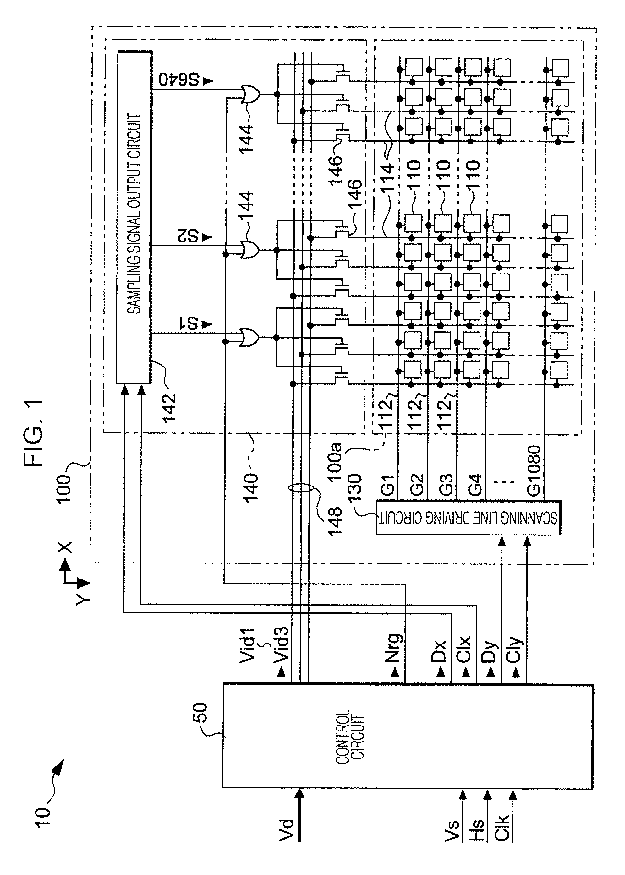
[0026]FIG. 1 is a block diagram showing the whole structure of an electro optical device according to the embodiment. As shown in FIG. 1, the electro optical device 10 is roughly divided into a control circuit 50 and a display panel 100. The control circuit 50 is a circuit module independent from the display panel 100 and connected to the display panel 100 by, for example, an FPC (flexible printed circuit) substrate.

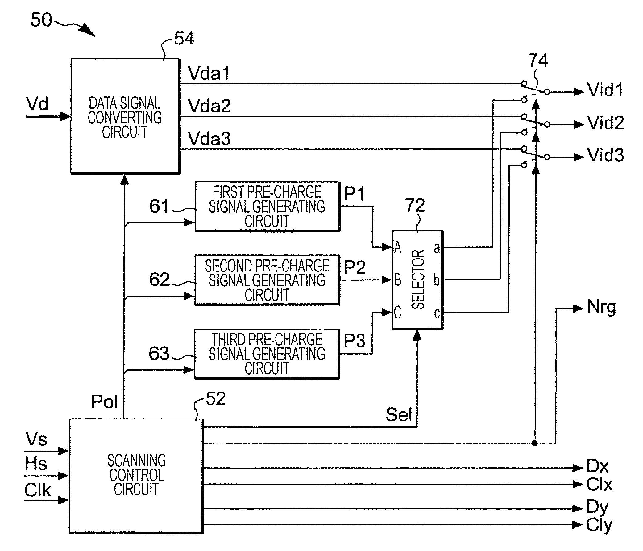
[0027]The control circuit 50 controls each unit of the display panel 100 in accordance with a vertical synchronization signal Vs, horizontal synchronization signal Hs, and a clock signal Clk supplied from an exterior upper-level circuit (not shown) and supplies data signals converted to three channels of analog from image data Vd of digital or supplies signals for pre-charge of three channel to image signal lines 148 of the display panel 100.

[0028]Note that the...


PUM


Abstract

A driving method of an electro optical device includes pre-charging “m” columns of data lines belonging to each block to at least two different voltages before selecting the block. In addition, the combination of the at least two different voltages pre-charged to the “m” columns of data lines belonging to each block is switched each time a scanning line is selected.

Description

BACKGROUND[0001]1. Technical Field[0002]The present invention relates to a technique for obscuring deterioration of display quality when so called phase developed data signals are sampled to data lines.[0003]2. Related Art[0004]In recent years, there have been efforts for realizing a higher definition of display images such as high vision. The higher definition of the display images may be realized by increasing the number of scanning lines and the number of data lines. However, since a frame frequency is fixed, an increase in the number of scanning lines may shorten one horizontal scanning period and an increase in the number of data lines may shorten a period for selecting the data lines in the dot sequential method. Therefore, when attempting to achieve higher definition, it may not be possible to secure a sufficient time for supplying the data signals to the data lines, thereby making the writing of data to the pixels insufficient.[0005]In order to solve the insufficient writing...

Claims


Application Information

Patent Timeline
IPC IPC(8): G09G5/00
CPCG09G3/3614G09G3/3648G09G2310/0218G09G2310/0251G09G3/36G02F1/133G09G3/20
Inventor AOKI, TORU
Owner SEIKO EPSON CORP
Why Eureka
Try Eureka