RFID tag reader
a technology of rfid tags and readers, applied in the field of radio frequency identification, can solve the problems of affecting installation workability, unable to achieve high precision of reading rfid tags, and complicating installation workability, so as to achieve high installation workability and high reading precision
- Summary
- Abstract
- Description
- Claims
- Application Information
AI Technical Summary
Benefits of technology
Problems solved by technology
Method used
Image

Examples
first embodiment
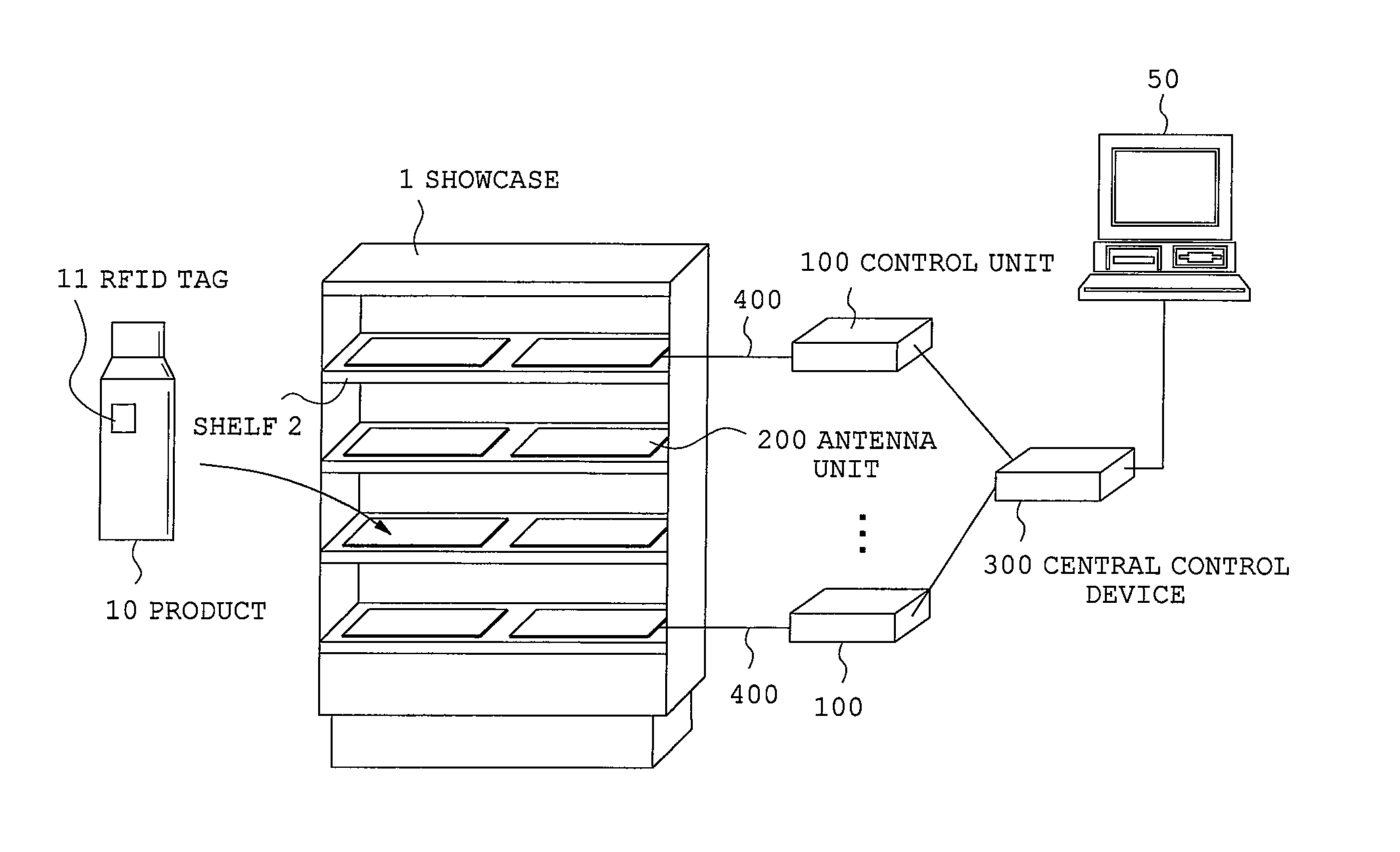
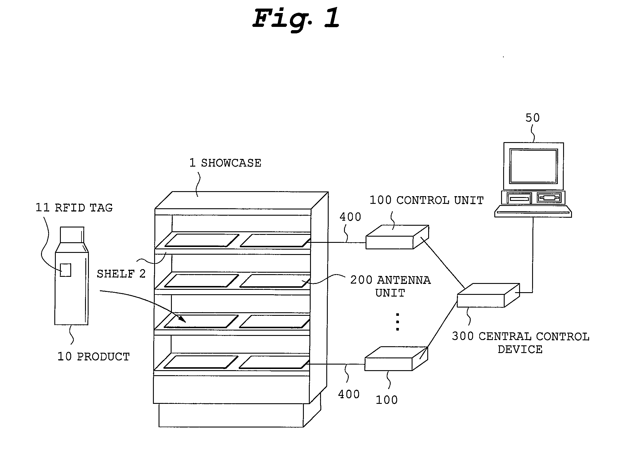
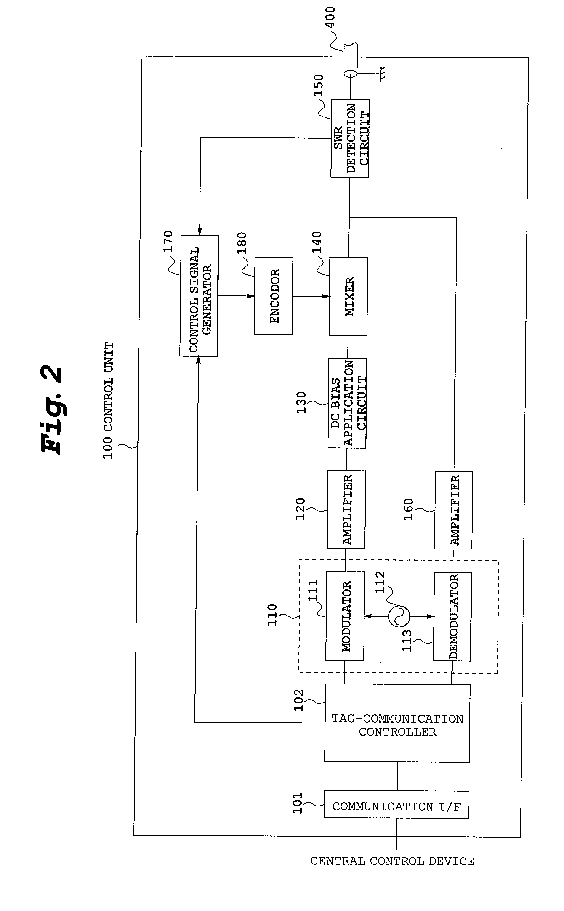
[0025]Referring now to accompanying drawings, description will be made on an RFID tag reader according to a first embodiment of the present invention. FIG. 1 is an overall configurational view of an RFID tag reader, FIG. 2 is a functional block view of a control unit, FIG. 3 is a configurational view of an antenna unit and FIG. 4 is a functional block view of an antenna unit.
[0026]The reader according to the present embodiment is assumed to be used for applications of reading unique numbers from RFID tags 11 affixed on products 10 displayed on a show case 1 as unique identifier of the RFID tags 11. Generally, product shelves 2 of the show case 1 are made of metal having a severe influence on formation of an electromagnetic field. On the product shelves 2, products 10 of various types of materials are displayed and the number of displays for products 10 constantly change. Accordingly, to read RFID tags 11 on all products 10 displayed on product shelves 2, adjustment work is required ...
second embodiment
[0043]Referring next to the accompanying drawings, description will be made on an RFID tag reader according to a second embodiment of the present invention. A difference of the present embodiment from the first embodiment is that a plurality of antenna units 200 are connected with one control unit 100. Specifically, as illustrated in FIG. 11, a control unit 100 is connected with the first antenna unit 200 through a coaxial cable 400, and the first antenna unit 200 is connected with a second antenna unit 200′ through a coaxial cable 401. More specifically, the plurality of antenna units 200 are daisy-chain-connected with the one control unit 100.
[0044]In the RFID tag reader, a tag communication controller 102 of the control unit 100 makes a control signal for antenna switching include numbers for identifying each of the antenna units 200, 200′. An antenna switching controller 254 of the respective antenna units 200, 200′ has a storage portion for storing own identification numbers or...
PUM
 Abstract
Description
Claims
Application Information
 - R&D
- Intellectual Property
- Life Sciences
- Materials
- Tech Scout
- Unparalleled Data Quality
- Higher Quality Content
- 60% Fewer Hallucinations
Browse by: Latest US Patents, China's latest patents, Technical Efficacy Thesaurus, Application Domain, Technology Topic, Popular Technical Reports.
© 2025 PatSnap. All rights reserved.Legal|Privacy policy|Modern Slavery Act Transparency Statement|Sitemap|About US| Contact US: help@patsnap.com