Intelligent adaptive x-ray imaging system

a x-ray imaging and adaptive technology, applied in the field of x-ray imaging system, to achieve the effect of improving diagnostic information

Inactive Publication Date: 2008-09-25
UCL BUSINESS PLC
View PDF4 Cites 2 Cited by
  • Summary
  • Abstract
  • Description
  • Claims
  • Application Information

AI Technical Summary

Benefits of technology

[0007]Thus, the invention provides a method and arrangement which enables the subject of the x-ray imaging system to be so exposed, as to provide improved diagnostic information. To this end, the image from the radiated item is firstly analyzed in order to assess its diagnostic quality and subsequently the exposure conditions are adapted accordingly in real-time.

Problems solved by technology

Thus, although the detector may be optimally exposed the object may not be.

Method used


Image

  • Intelligent adaptive x-ray imaging system
  • Intelligent adaptive x-ray imaging system
  • Intelligent adaptive x-ray imaging system

Examples


Embodiment Construction

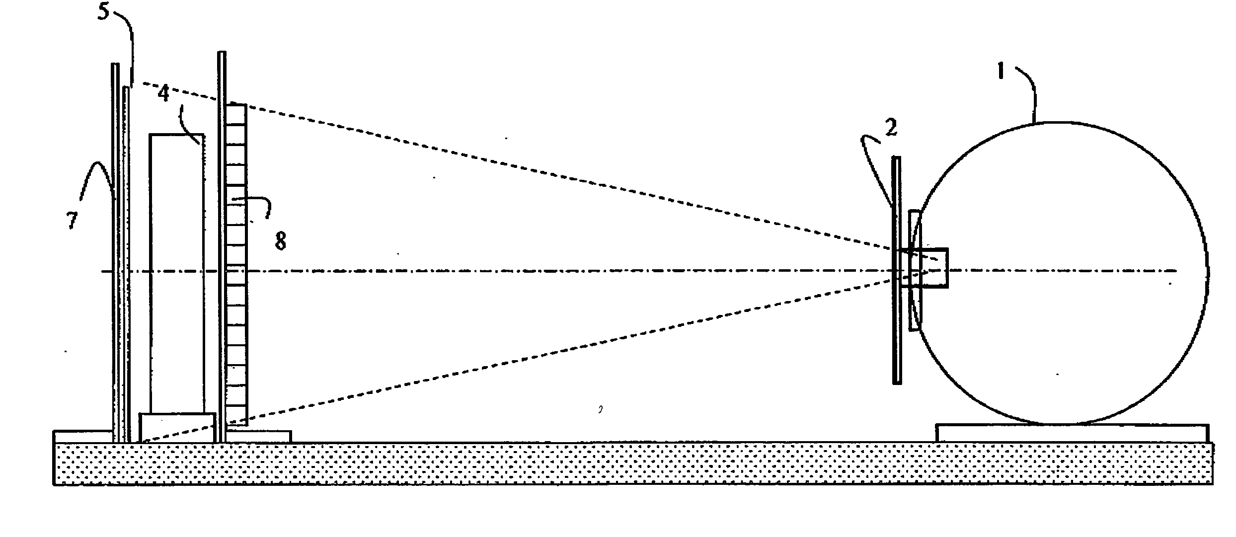
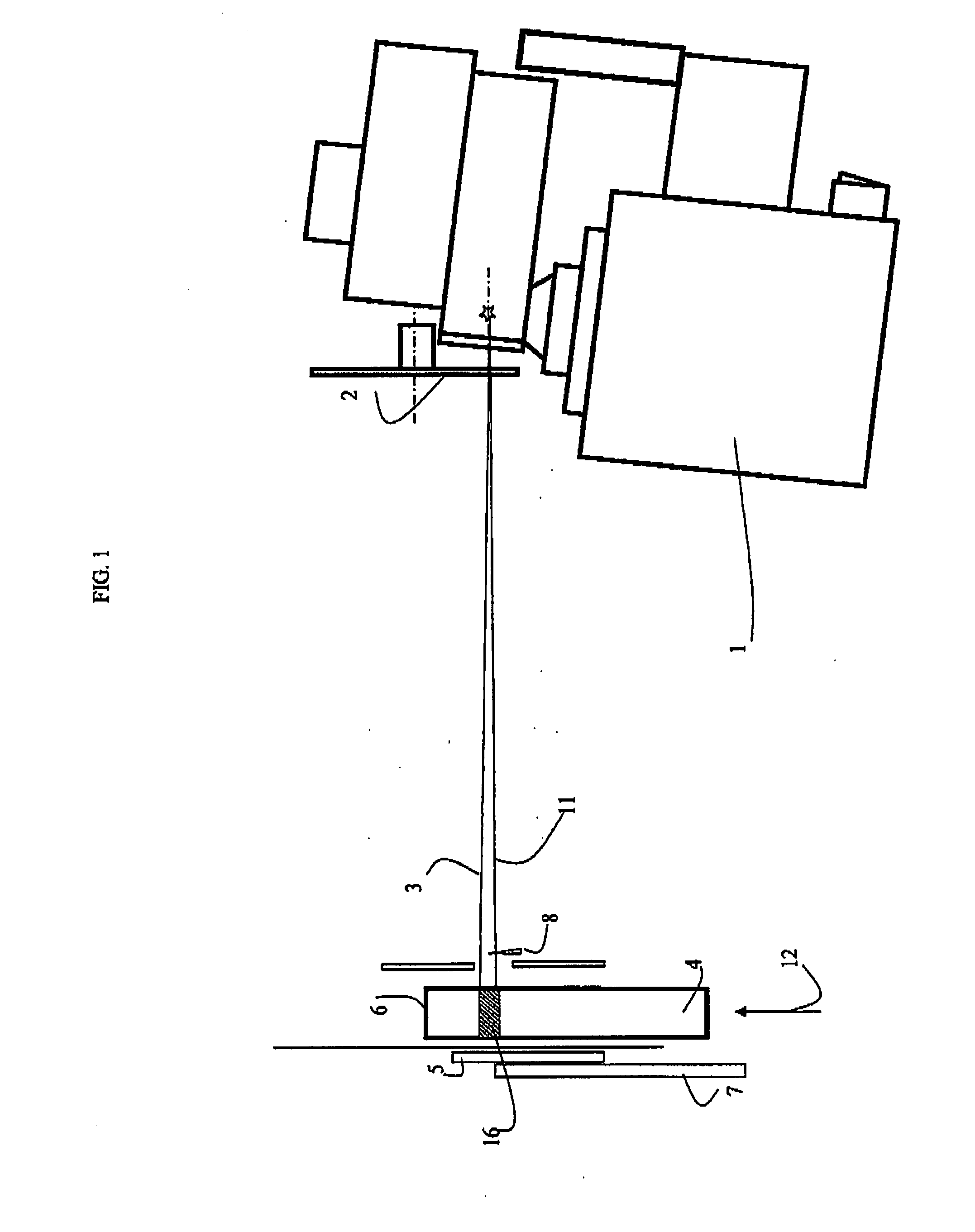
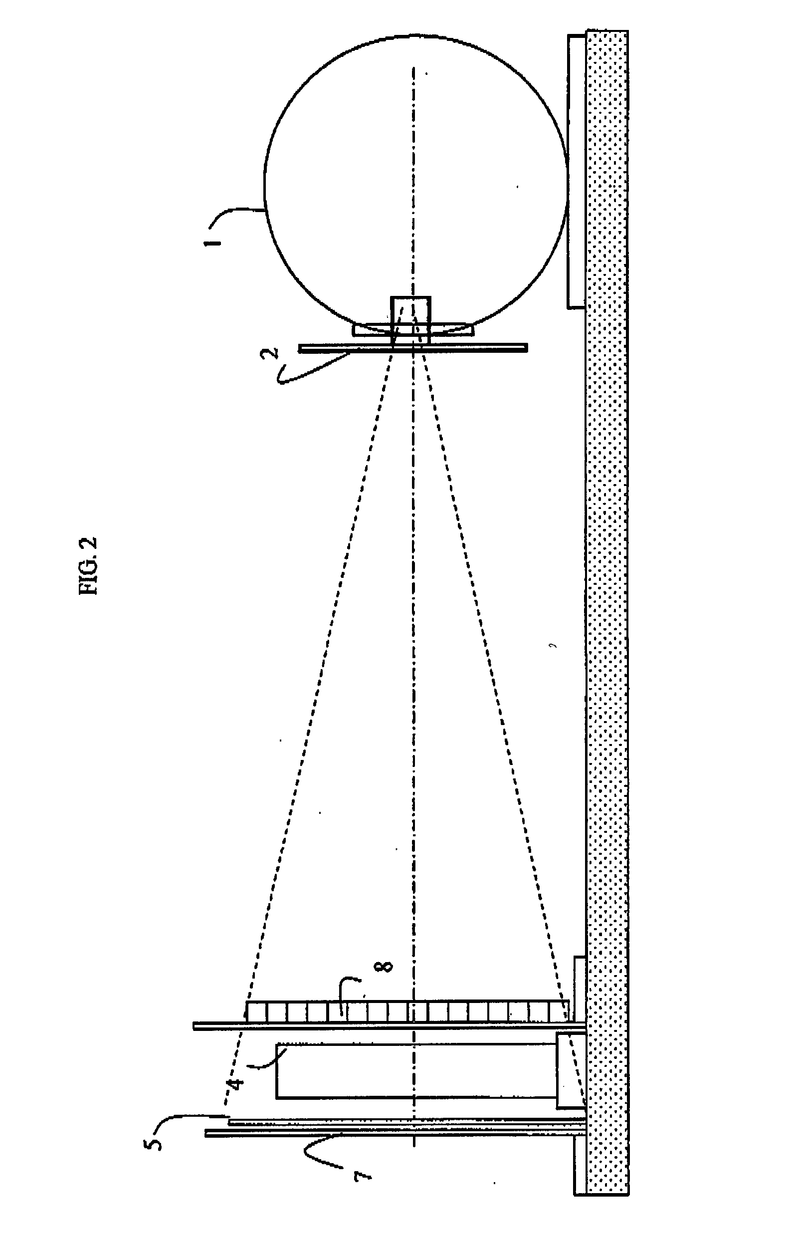
[0017]Referring to FIGS. 1 and 2, a source of ionizing radiation 1, in the embodiment X-rays, produces a conical beam, that is divided into two fan beams 3, 11 by the collimator system 2. These beams are labeled scout beam 3 and second beam 11, the latter may also referred to as ‘I-ImaS’ beam.

[0018]These beams 3, 11 and respective sensors 5 arranged to detect each beam are scanned across an object 4 to be imaged 4 such that the second beam follows the scout beam. This may be done by moving the beams, but in the embodiment the object 4 is moved in the direction of arrow 12 (FIG. 1) keeping the collimator 2, beams and sensors 5 fixed.

[0019]In a summary of the method, the system carries out the method illustrated in flow chart form in FIG. 5.

[0020]The system generates 20 first and second imaging beams and scans 22 the first and second imaging beams over the object with the second beam following the first beam. The system records 24 an image of the object with the first beam over a plur...


PUM


Abstract

A method and an arrangement for an intelligent adaptive x-ray imaging system, in which the exposure conditions of the object to x-rays is dynamically controlled and optimized in real-time in order to provide the optimum diagnostic information. The arrangement splits the imaging beam into two separate fan beams that scan over the object in a single pass, where the first beam (scout) collects information from the object, that is analyzed to control the intensity or spectral quality or spatial distribution of the second beam (I-ImaS). The CMOS image sensors deployed in the arrangement are able to process detected information either on-chip or within a field programmable gate array, so as to compute a measure related to the diagnostic value of the information.

Description

TECHNICAL FIELD OF THE INVENTION[0001]The present invention relates to an x-ray imaging system.BACKGROUND OF THE INVENTION[0002]Imaging systems able to control the X-ray source output are known to exist, in particular the use of automatic exposure control (AEC) is available on many systems to avoid over exposure. See for example D. B. Plewes, E. Vogelstein, ‘A scanning system for chest radiography with regional exposure control: Practical implementation’, Medical Physics, volume 10 number 5, 655-663, 1983.[0003]Similarly, computed tomography (CT) systems adjust the exposure at each view to ensure the dynamic range of response of the detector array is used most efficiently, as set out in L. Jangland, E. Helmius, ‘Automatic exposure control on CT systems’, Radiology, volume 201, 792S, 1996, U. Nyman, T. L. Ahl, M. Kristiansson, L. Nilsson, S. Wettemark, ‘Patient-circumference-adapted dose regulation in body computed tomography. A practical and flexible formula’, Acta Radiologica, volu...

Claims


Application Information

Patent Timeline
Patent Type & Authority Applications(United States)
IPC IPC(8): G21K3/00G21K1/00
CPCA61B6/00A61B6/4035G21K1/10A61B6/488A61B6/502A61B6/469
Inventor SPELLER, ROBERTROYLE, GARY
Owner UCL BUSINESS PLC
Why Eureka
Try Eureka