Design Structure for a Duty Cycle Correction Circuit
a duty cycle and design structure technology, applied in the field of design structure, can solve the problems that fixed duty cycle may not necessarily result in optimal operating conditions in all applications, and achieve the effect of less change in dcc correction range and more toleran
- Summary
- Abstract
- Description
- Claims
- Application Information
AI Technical Summary
Benefits of technology
Problems solved by technology
Method used
Image
Examples
Embodiment Construction
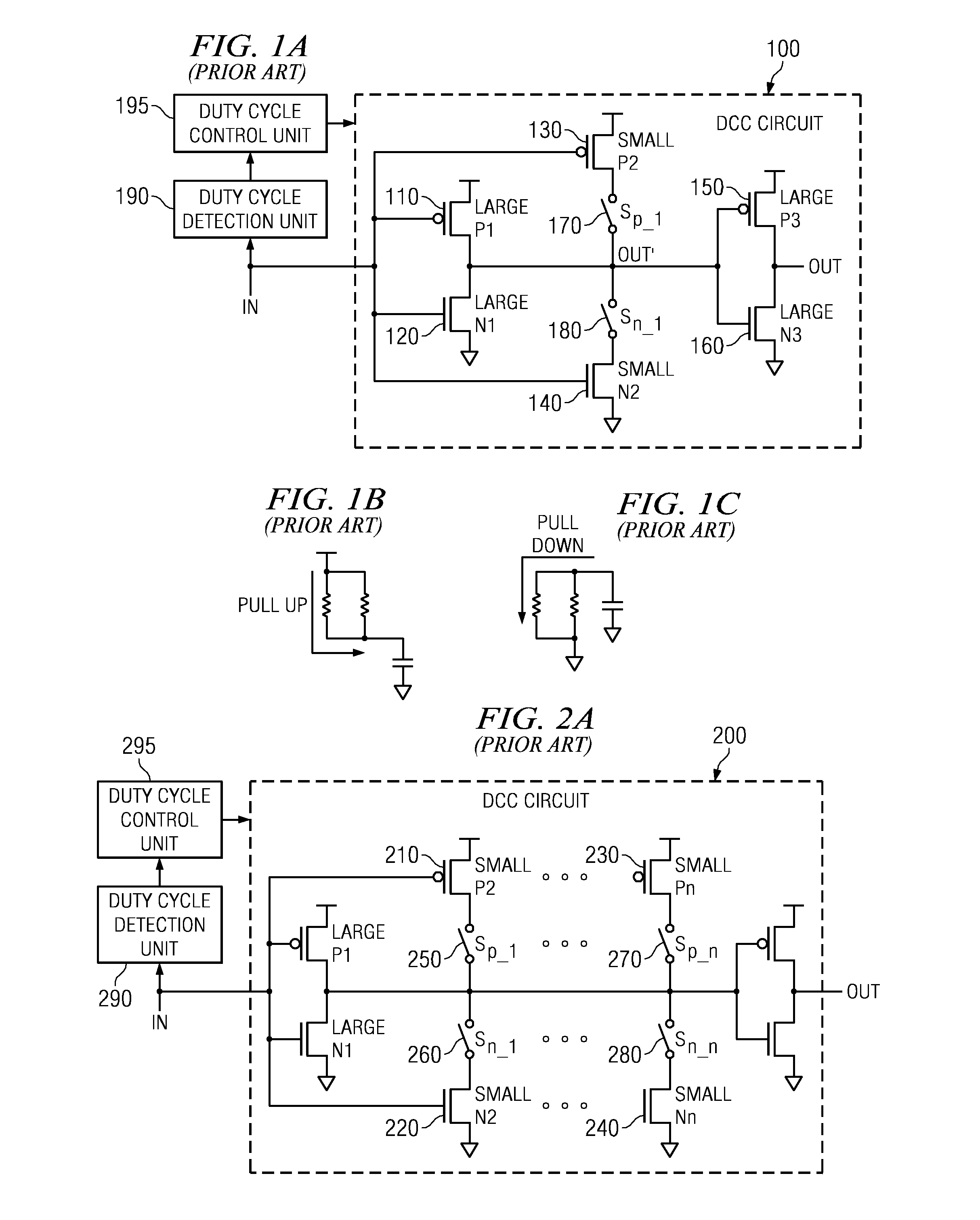
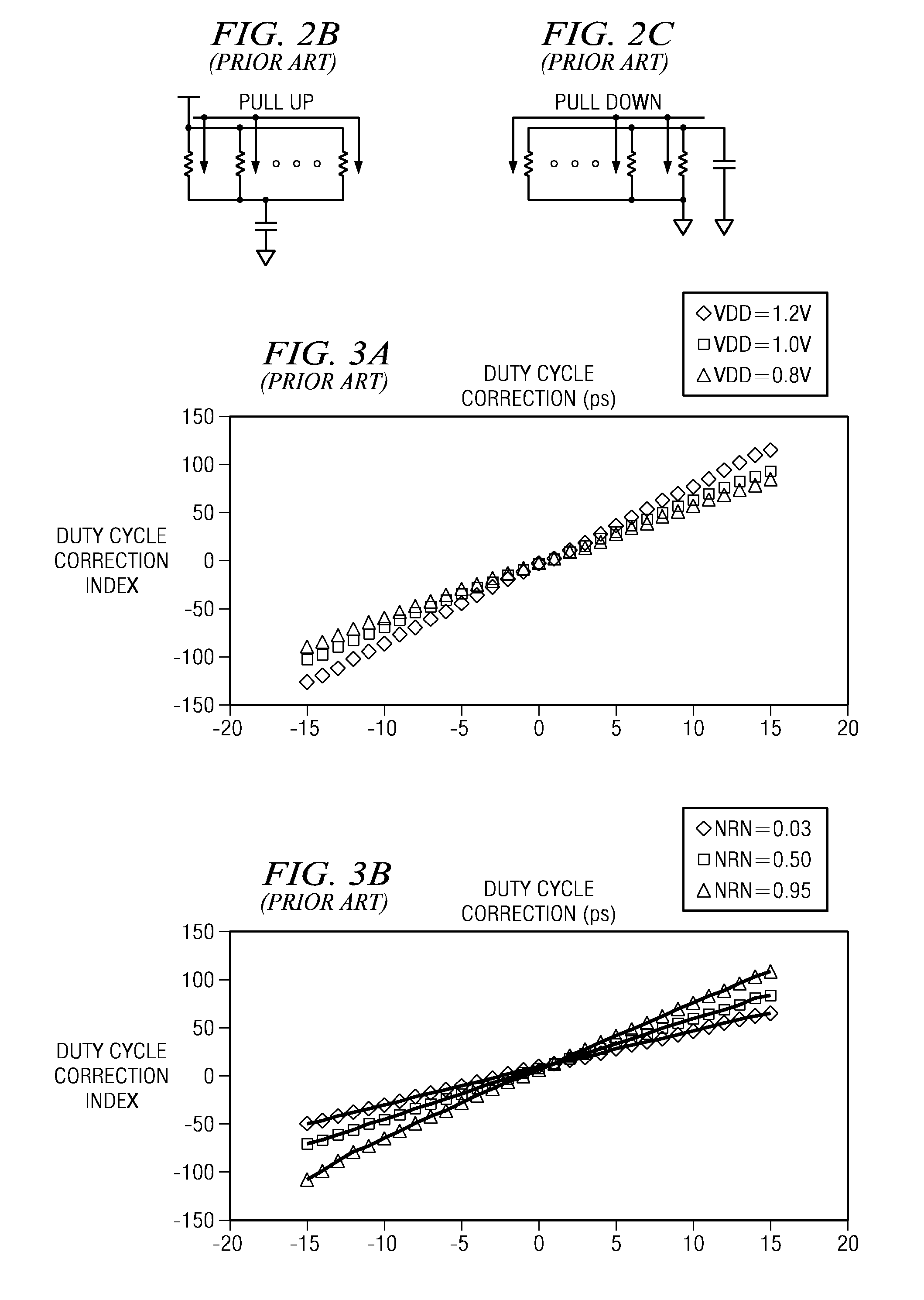
[0064]The illustrative embodiments provide a duty cycle correction (DCC) circuit that utilizes linear resistors rather than FETs to provide the duty cycle correction. Since the linear resistors are less sensitive to operating voltage and process, the resulting DCC circuit is more tolerant of variations in operating voltage and process. One application of such a DCC circuit is to provide varying duty cycles and non-50% duty cycles to circuitry of a data processing device where such varying or non-50% duty cycles provide more optimal performance.
[0065]FIG. 4A is an exemplary diagram illustrating a duty cycle correction (DCC) circuit in accordance with one illustrative embodiment. As shown in FIG. 4A, the DCC circuit 400 includes a first pair of FETs comprising a first PFET 410 and a first NFET 420. The first pair of FETs are part of the inverter circuit that provides the duty cycle correction. The first PFET 410 and NFET 420 preferably have large resistance values. Again, the terms “l...
PUM
 Abstract
Description
Claims
Application Information
 - R&D
- Intellectual Property
- Life Sciences
- Materials
- Tech Scout
- Unparalleled Data Quality
- Higher Quality Content
- 60% Fewer Hallucinations
Browse by: Latest US Patents, China's latest patents, Technical Efficacy Thesaurus, Application Domain, Technology Topic, Popular Technical Reports.
© 2025 PatSnap. All rights reserved.Legal|Privacy policy|Modern Slavery Act Transparency Statement|Sitemap|About US| Contact US: help@patsnap.com


