
Implantable Medical Device with a Voltage Protection Circuit

a medical device and voltage protection technology, applied in the field of implantable medical devices, can solve the problems of severe damage to the functions of the medical device, impaired conventional solution, and increased sensitivity of the implantable device to misoperation,

Active Publication Date: 2008-09-18
ST JUDE MEDICAL
View PDF7 Cites 10 Cited by
  • Summary
  • Abstract
  • Description
  • Claims
  • Application Information

AI Technical Summary

Benefits of technology

[0009]Thus, an object of the present invention is to provide an improved protection circuit that can effectively protect the internal circuits of an implanted medical device against undesired voltage pulses caused by exposure to defibrillation and / or electrocautery received by the antenna, for example, at galvanic exposure against tissue and be conducted further into the electronic circuits and RF telemetry circuits of the medical device.
[0010]Another object of the present invention is to provide such a protection circuit that can be implemented in an implanted medical device in a space efficient manner.
[0011]A further object of the present invention is to provide such a protection circuit that can be implemented in an implanted medical device in a cost efficient manner.
[0014]This solution provides several advantages over the conventional technique. One advantage is that, since the filter circuit, i.e. the capacitor element, is integrated in the antenna feedthrough, valuable space in the medical device can be saved. Another advantage is that the risk of possible interference leakage into the hermetically sealed device can be significantly reduced due to the fact that the filter circuit, i.e. the capacitor, is arranged in the feedthrough and, thus, prevents the external voltage transients or pulses from entering into the medical device. Furthermore, combining two functions, i.e. the hermetic seal and the galvanic isolation, in the feedthrough entails cost savings, which also is an advantage in comparison with the known technique.

Problems solved by technology

However, with this increasing sophistication has come a concomitant increase in sensitivity of the implantable devices to misoperation due to external influences such as defibrillation, electrocautery, and the like.
This may cause the medical device to falsely identify the interference as being of cardiac origin and give rise to, for example, an erroneous output rate, or in worst case, it may change the state of or destroy components of the circuits, which, in turn, may severely damage the functions of the medical device.
However, this conventional solution is impaired with a number of drawbacks.
For example, the filter circuit, i.e. the capacitor, requires extra space, which may be a problem in implantable devices, such as cardiac pacemakers, where internal space is limited.
Moreover, since the external interference signals are transferred into the hermetically sealed device, they may give rise to interference leakage within the device.

Method used


Image

  • Implantable Medical Device with a Voltage Protection Circuit
  • Implantable Medical Device with a Voltage Protection Circuit
  • Implantable Medical Device with a Voltage Protection Circuit

Examples


Embodiment Construction

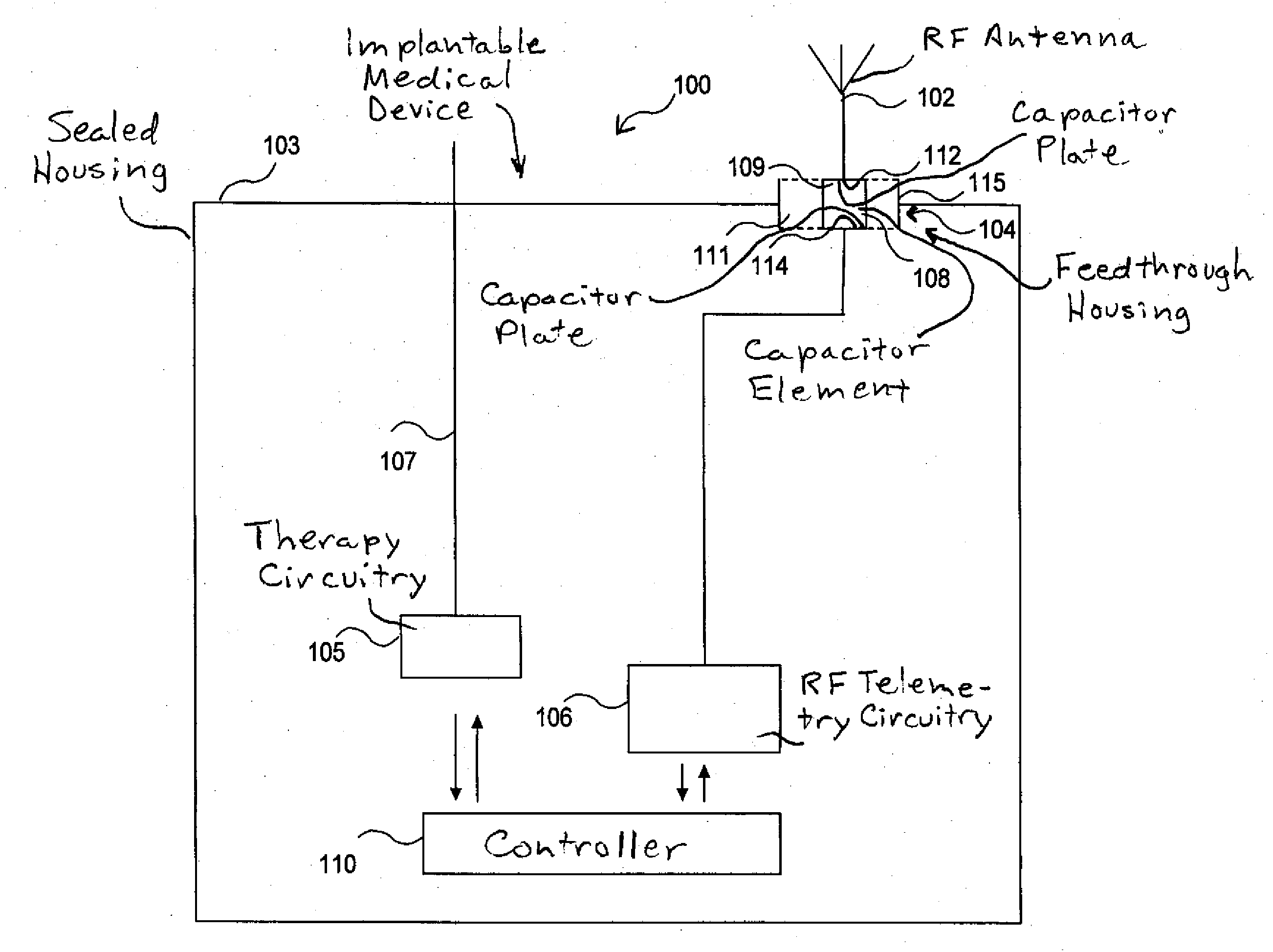
[0035]With reference first to FIG. 1, an implantable medical device (IMD) 100 having a serial capacitive feedthrough adapted to protect the electronic circuitry of the device against undesired voltage transients caused by exposure to defibrillation and / or electrocautery conducted into the device via an antenna or a part of the medical device capable of functioning as an antenna being in tissue contact and connected to electronic circuitry of the device in accordance with the present invention will be described.

[0036]The IMD 100 is provided with an antenna 102 for communication with external devices such as an external programmer. Preferably, the antenna 102 is suitable for radiating and receiving far-field electromagnetic radiation. It should be noted that the housing effectively is a part of the antenna and affects the radiation properties of the antenna 102. The housing is further in contact with the tissue. The IMD 100 includes a hermetically sealed housing 103 provided with an a...


PUM


Abstract

An implantable medical device has a hermetically sealed housing with at least one feedthrough therein for a conductive path between an RF antenna carried by the housing, and an RF telemetry circuit contained in the housing. The feedthrough has a feedthrough housing with a capacitor element therein having first and second capacitor plate configurations, with a first of the capacitor plate configurations being connected to the RF antenna and a second of the capacitor plate configurations being connected to the RF telemetry circuit. The feedthrough functions both as a hermetic seal and as a galvanic isolation for voltage protection of the components of the RF telemetry circuit, and other circuitry in the sealed housing connected thereto.

Description

BACKGROUND OF THE INVENTION[0001]1. Field of the Invention[0002]The present invention generally relates to implantable medical devices such as implantable cardiac pacemakers and implantable cardioverter / defibrillators, and in particular to a capacitive feedthrough for filtering off external interference signals, e.g. defibrillation signals, in order to protect the electronic circuits and telemetry circuits of such an implanted device.[0003]2. Description of the Prior Art[0004]Implantable medical devices, including cardiac rhythm management devices such as pacemakers and implantable cardioverter / defibrillators, typically have the capability to communicate data with an external programmer via a radiofrequency telemetry link. A clinician may use such an external programmer to program the operating parameters of an implanted medical device. For example, the pacing and other operating characteristics of a pacemaker are typically modified after implantation in this manner. Modern implanta...

Claims


Application Information

Patent Timeline
Patent Type & Authority Applications(United States)
IPC IPC(8): A61F2/02A61N1/00
CPCA61N1/3754A61N1/3718
Inventor DAHLBERG, KENNETH
Owner ST JUDE MEDICAL
Learn More