Impeller with Anti-vapor lock mechanism

Inactive Publication Date: 2008-09-18
KEEPALIVE
View PDF7 Cites 3 Cited by
  • Summary
  • Abstract
  • Description
  • Claims
  • Application Information

AI Technical Summary

Benefits of technology

[0019]It is an object of the present invention to provide an impeller designed to prevent air-lock of the pump.
[0020]It is yet another object of the present invention to provide an impeller, which prevents air lock of the pump and does not require constant monitoring by the operator.
[0021]It is yet another object of the present invention to provide a mechanism by which air-lock may be prevented in currently available pumps.
[0025]However, once air is introduced into the impeller cavity, the impeller energy is diverted to first expanding air in the negative pressure side of the impeller, and then re-compressing air on the downstream side of the impeller. Further, as the volume of air is increased (due to the negative pressure) on the inlet side, this expanded air displaces the liquid, reducing the amount of water sucked into the impeller cavity. As the air exits the impeller cavity, it is compressed to reduce volume; this constant compressing having the end effect of reducing the output at the downstream side of the impeller.

Problems solved by technology

This energy, however, provides several undesired side effects such as air-locking of the pump.
Lower pressures in the impeller center axis are caused by variations in velocity of the fluid and friction losses as the fluid enters the impeller.
During air locking, the pump not only fails to serve its basic purpose of pumping the liquid, but also may experience excessive noise and vibrations, internal damage, leakage from the seal and casing, bearing failure, etc.
The extent of the air-locking damage can range from a relatively minor amount of pitting after years of service to catastrophic failure in a relatively short period of time.
In summary, air-locking is an abnormal condition on the pump that can result in loss of production, equipment damage, and worst of all, personnel injury.
However, this device does not proactively clear the air-lock, and the impeller pump may remain air-locked during the interval between testing for air-lock.
The device of Kusiak et al. is mechanically complex, and in order to function properly, the device requires the divider wall to create a positive and negative pressure (as opposed to a normal flow of water), which actually reverses the flow of water, thereby allowing any trapped air to escape.
These projections cut through the liquid, which has been centrifuged to the outer annulus, thus causing a turbulence, which draws a portion of the liquid into the body of the impeller for mixing with trapped air.
Such a system has a number of attendant problems.
The pump may be operated upside down near the surface for periods of time without damage; however, if operated upside down at depth for any length of time, air in the motor housing will exit through the seal between the motor shaft and the impeller, and water will enter the motor housing, thereby causing damage.
Further, if the pump is operated on the surface, oxygenation of the water will occur near the surface of the tank, and the lower reaches of the bait well will not be aerated.
Such a design cannot optimize the air / water mixture for maximum oxygenation of the pump at every given depth.
As a result of these design constraints, the oxygenation efficiency is adequate, but much less than optimal.
This high flow rate would render the aerator impractical for use in small applications such as bait wells, since the high turbulence would be injurious to the baitfish.
However, where the object is to achieve a high rate of mixing of air into a relatively small volume of water, as would be required in a bait well application, this high-speed centrifugal aerator is entirely unsuitable.
Finally, the venturi gas inlets must be narrow to be effective as the pump is cycled through many ON-OFF periods, during which the venturi gas inlets will be flooded and dried, resulting in sedimentation and encrustation.
The venturi jets will require attention and cleaning over time.

Method used


Image

  • Impeller with Anti-vapor lock mechanism
  • Impeller with Anti-vapor lock mechanism
  • Impeller with Anti-vapor lock mechanism

Examples


Embodiment Construction

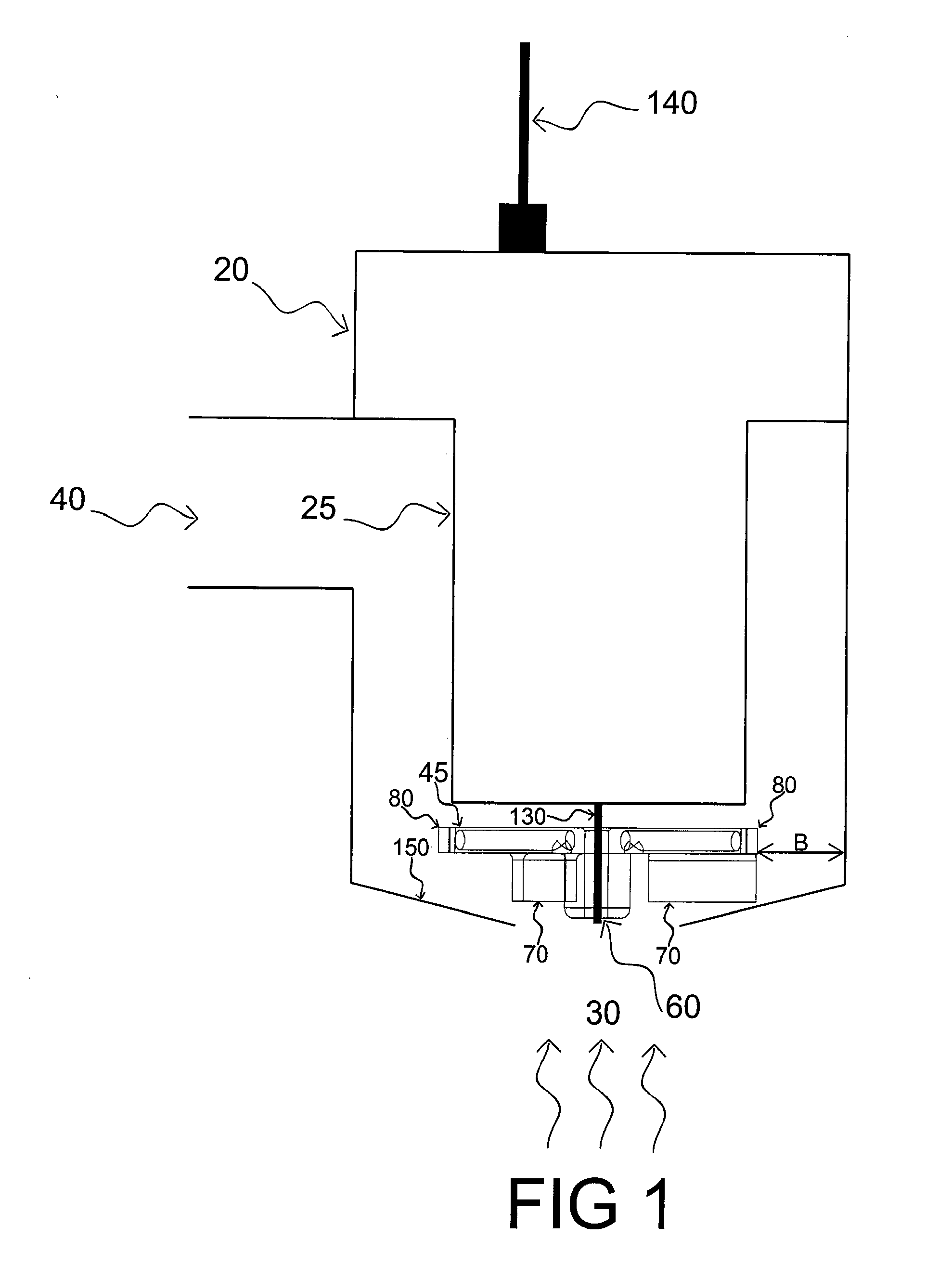
[0057]The present invention is directed to a pump for pumping water, sewage, or other liquid material from one location to another. The pump includes an impeller, or impeller that is rotated in moderately close proximity to a stationary plate or stator. The stationary plate has a central, coaxial inlet through which liquid passes, and is thereafter conveyed by centrifugal force along the impeller-plate spacing to an outlet at the periphery of the impeller and the plate.

[0058]The pump may be any conventionally available pump such as centrifugal pump, an impeller pump, or a mixed flow. Preferably, the pump is a centrifugal pump, such as a centrifugal rotary bilge pump that is well known in the art.

[0059]Centrifugal pumps are classified into three categories—submersible, dewatering and trash.

[0060]Submersible pumps offer contractors versatility on the job site. These pumps are, by definition, submersible in water containing solids up to one-quarter inch in diameter and less than 10 per...


PUM


Abstract

An impeller for preventing air-lock in a pump, the impeller in its basic embodiment includes a top plate, the top plate having a center axis and a peripheral edge, a plurality of vanes, each vane attached to the top plate, at least one small protrusion projecting from the periphery of the top plate, and at least one ventilation channel having an outlet located near the protrusion, and an inlet located near the center axis of the top plate. The present invention also contemplates a centrifuge pump and an aerator device having the impeller of the present invention.

Description

BACKGROUND OF THE INVENTION[0001]1. Field of the Invention[0002]The present invention is directed to an impeller, and more particularly, an impeller provided with an air-release mechanism to prevent air-lock of a pump.[0003]2. Description of the Related Art[0004]Rotary pumps are well known structures employed to pump fluids from one location to another. Rotary pumps have been developed for a number of different uses, ranging from fire engine apparatus to volumetric dosing of commercially important materials. Rotary pumps may be classified according to structural features of their material propelling elements. An example of the most commercially important types of rotary pump is the centrifuge pump.[0005]Most centrifuge pumps comprise a generically cylindrical casing and an impeller, or a plurality of impellers mounted inside the casing to drive a fluid through the pump. The pumps typically operate by taking in a fluid and adding energy from the fluid by kinematics means; thus, the f...

Claims


Application Information

Patent Timeline
IPC IPC(8): F04D9/00
CPCF04D29/2277F04D9/003
Inventor VENTO, THOMAS JOSEPH
Owner KEEPALIVE
Why Eureka
Try Eureka