Eureka AIR delivers breakthrough ideas for toughest innovation challenges, trusted by R&D personnel around the world.

Flame Imitation Manufacturing Device of an Electrical-Heated Fireplace

Inactive Publication Date: 2008-09-18
WANG ZHUHONG
View PDF8 Cites 0 Cited by
  • Summary
  • Abstract
  • Description
  • Claims
  • Application Information

AI Technical Summary

Benefits of technology

[0003]The object of this invention is to overcome the above shortcomings in the prior art by providing a flame imitation manufacturing device with flame images higher in fidelity and stronger in authenticity.
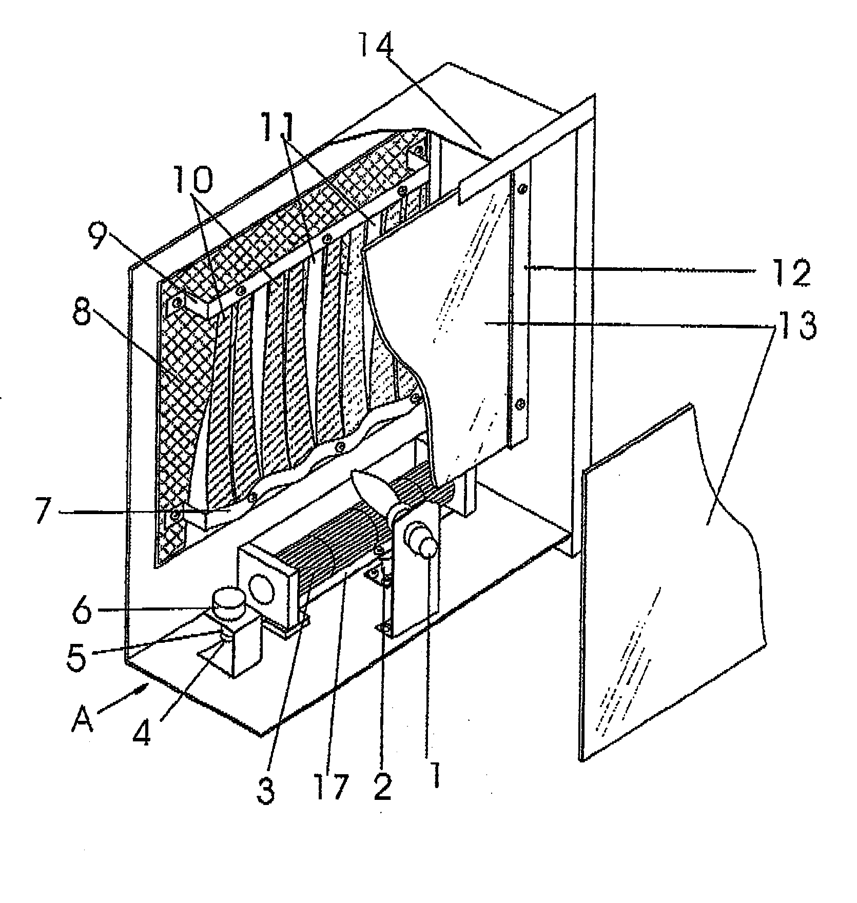
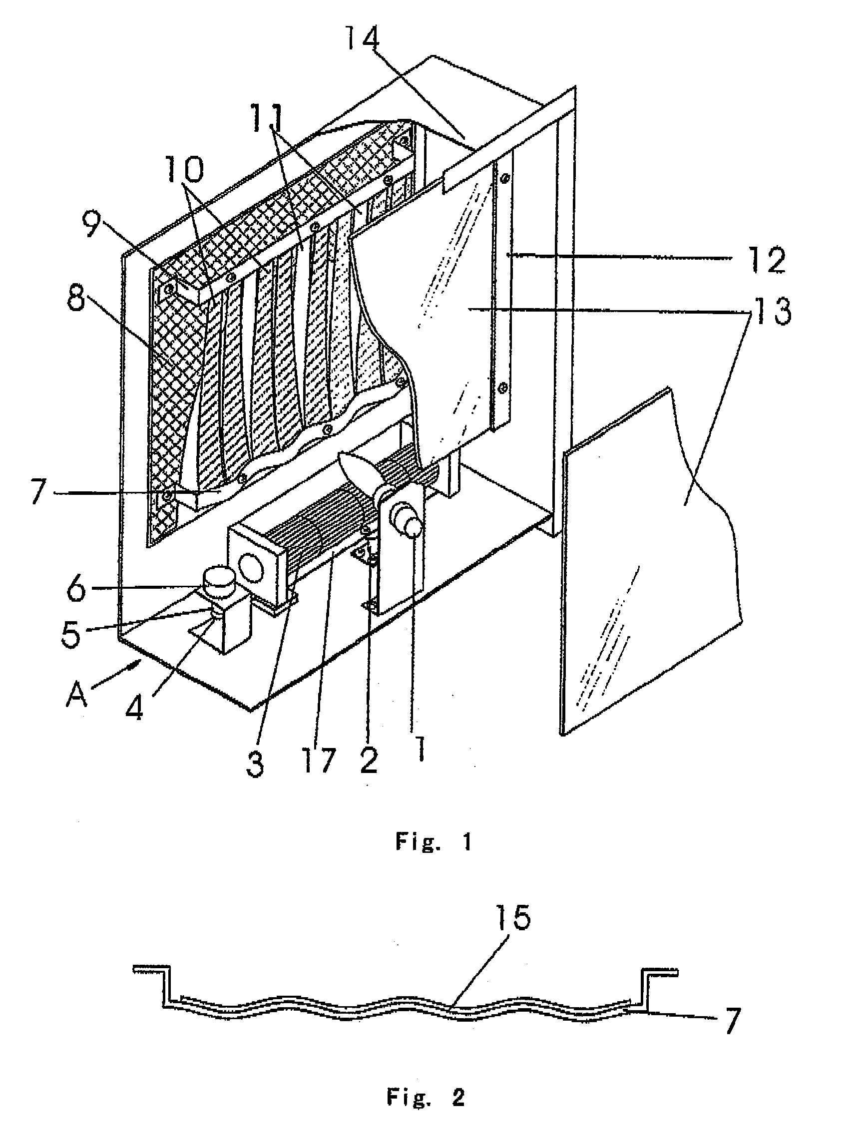
[0005]That designing said lower strip bar for mounting ribbons to be wave-like changes the flat and vertical cooperation of ribbons, improves the reflective surface of ribbons from a plane to a cambered surface with richer reflective angles, meanwhile enhances the longitudinal-axially reversing of ribbons, and improves the extent of variation of flame images as well.
[0007]Compared with previously mentioned products belonging to the same category, this invention is advantageous in that supplying wind by utilizing the swinging of said fan improves the flying state of ribbons so as to make the image state of burning flames more vivid, greatly enhances the authenticity of flames, and thus is adaptable to various flame imitation appliances.

Problems solved by technology

Said device has the following shortcomings: the direction of wind blasted to ribbons by the cross flow fan which is fixed on a base plate of the housing is stationary, the flying intensity of ribbons is consequently unchanged, which results in slight change, low fidelity and insufficient authenticity in the general contour of flame images of ribbons.

Method used


Image

  • Flame Imitation Manufacturing Device of an Electrical-Heated Fireplace
  • Flame Imitation Manufacturing Device of an Electrical-Heated Fireplace
  • Flame Imitation Manufacturing Device of an Electrical-Heated Fireplace

Examples


embodiment 1

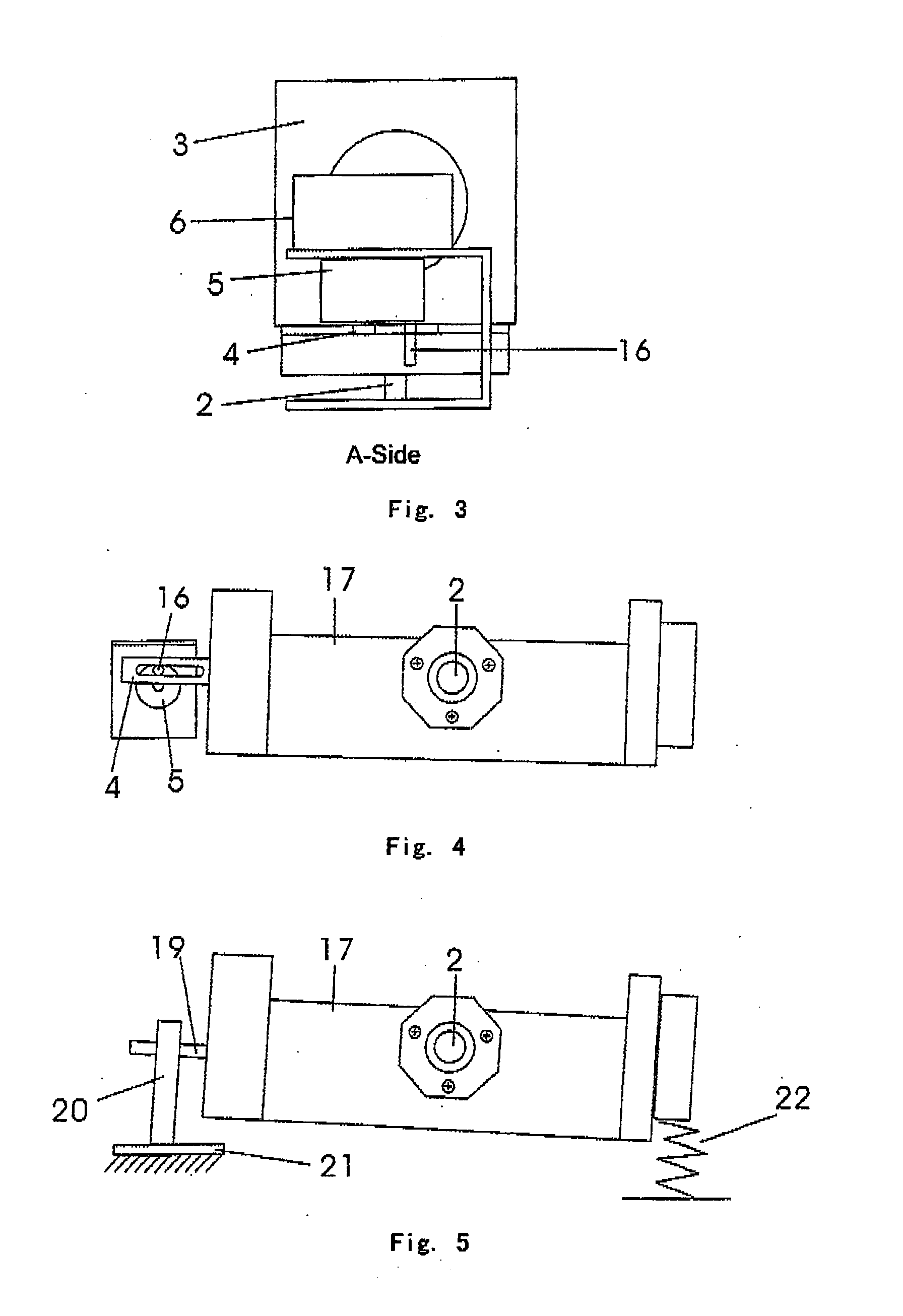
[0014]As shown in FIGS. 1-4, in this embodiment the swinging cross flow fan comprises a hinge post 2 fixed on a base plate of a housing 14, a fan itself 3 mounted on said hinge post 2, a guide recess gasket 4 fixed on one end of said fan, a drive motor 6 mounted on said housing, a transmission gear 5 fixed on a rotating shaft of said drive motor 6, and a transmission rod 16 with one end offset from said rotating shaft of the motor and fixed on the transmission gear 5 and the other end extending into the recess of said guide recess gasket 4. The rotation of the motor 6 brings the transmission rod 16 to drive the guide recess gasket 4 and thereby to drive the cross flow fan to swing. A light source 1 is fixed on the base plate of the housing 14. Ribbons which are configured alternately with golden ribbons 10 and argent ribbons 11 are mounted on a back plate of the housing and above the cross flow fan by means of an upper strip bar 9 and a lower strip bar 7, A light-transmitting glass ...

embodiment 2

[0016]Referring to FIG. 5, this embodiment differs the previous embodiment in that: an eccentric gear 20 is fixed on a motor shaft 19 of the fan itself, a baffle plate 21 is fixedly mounted on a position of the housing corresponding to the eccentric gear, a return spring 22 is mounted between the housing and the fan. The rotation of the motor drives the rotation of the eccentric gear 20, the fan swings around a hinge post 2 under the influence of the baffle plate 21 and returns to the original position by means of the return spring 22. The rotating speed of the eccentric gear may be adjusted by utilizing a variable speed mechanism.


PUM


Abstract

A flame imitation manufacturing device of a fireplace relates to a flame imitation manufacturing device for simulating the burning state in a fireplace in the field of household appliances. Said device comprises a housing, a cross flow fan and a light source mounted on a base plate of the housing, a simulated fire chamber mounted on a back plate of the housing, ribbons mounted on the back plate of the housing by means of upper and lower strip bars and above the cross flow fan, and a light-transmitting glass plate mounted on the housing and in front of said ribbons. This invention, characterized in that said cross flow fan is a swinging one, is advantageous in that supplying wind non-directively by utilizing the swinging of said fan improves the flying state of ribbons so as to make the image state of burning flames more vivid, greatly enhances the authenticity of flames and lowers the cost thereof, and thus is adaptable to various flame imitation electrical-heated fireplaces and electrical appliances.

Description

TECHNICAL FIELD[0001]This invention relates to a heating device in the field of household electrical appliances, particularly to a flame imitation manufacturing device for simulating fired states in a fireplace.BACKGROUND ART[0002]A Chinese utility model No. 99247747.6 has disclosed an electrical-heated decorating fireplace comprising a cast-iron housing, an electrical-heated pipe disposed within the housing, a circuit section, and a flame imitation device. Said flame imitation device of a fireplace comprises organic glasses, simple glasses, reflective films, flame imitation ribbons, electrical bulbs and a cross flow fan. Said device has the following shortcomings: the direction of wind blasted to ribbons by the cross flow fan which is fixed on a base plate of the housing is stationary, the flying intensity of ribbons is consequently unchanged, which results in slight change, low fidelity and insufficient authenticity in the general contour of flame images of ribbons. The electrical...

Claims


Application Information

Patent Timeline
IPC IPC(8): F24C7/00
CPCF24C7/004
Inventor WANG, ZHUHONG
Owner WANG ZHUHONG
Why Eureka
Eureka Blog
Learn More