Network system, node device and management server

a network system and management server technology, applied in the field of network systems, can solve problems such as deteriorating system performance, keeping erroneous detections arising, communication failures to be erroneously detected, etc., to achieve stable network operation and restrain detection delays

Inactive Publication Date: 2008-09-18
HITACHI LTD
View PDF6 Cites 25 Cited by
  • Summary
  • Abstract
  • Description
  • Claims
  • Application Information

AI Technical Summary

Benefits of technology

[0023]The invention can provide a network system, a node device, and a management server capable of avoiding, even if the packet transmission interval from the remote device is short, erroneous detection of a delay as a communication failure if the delay is not longer than the required margin time, which is the reference value for tolerating a delay. This enables stable network operation to be achieved by restraining unnecessary switch-over to a detour route.
[0024]The invention further has an advantage of restrain detection delays due to correction of the detection time by performing correction only when the uncorrected detection time is shorter than the required detection time (remote transmission time+required margin time).

Problems solved by technology

If in accordance with the rule the transmission interval is assumed to be 50 milliseconds and the detection multiplier to be 1 for instance, the tolerance for the delay will be 5 to 12.5 milliseconds, and there is a problem that, if a communication delay beyond the tolerance occurs, the failure of the packet to arrive within the waiting time on the receiving side will cause a communication failure to be erroneously detected.
Since route switch-over in Open Shortest Path First (OSPF) or Intermediate System-Intermediate System (IS-IS) imposes a heavy load, if switch-over is frequently caused to occur by erroneous detections, the performance of the system may deteriorate.
Therefore, it is required to keep erroneous detections arising from delays to the practicable minimum.

Method used


Image

  • Network system, node device and management server
  • Network system, node device and management server
  • Network system, node device and management server

Examples


Embodiment Construction

1. System Configuration

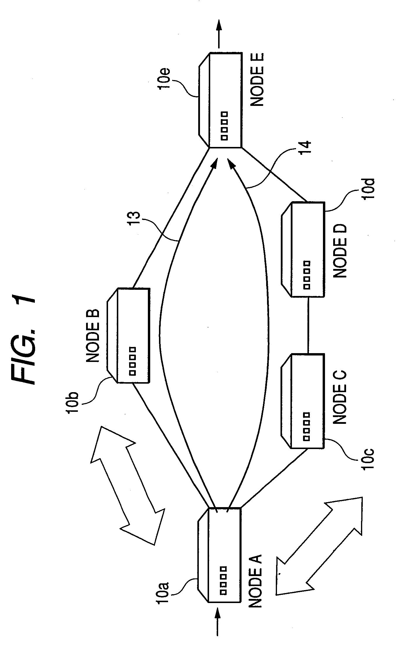
[0041]FIG. 1 shows an example of configuration of a communication failure detection system in one preferred embodiment of the invention.

[0042]The communication failure detection system (network system) is provided with, for instance, a plurality of node devices s 10 (hereinafter referred to simply as nodes).

[0043]When there are a route 13 via a node B (10b) and a route 14 via a node C (10c) and a node D (10d) as communication paths between a node A (10a) and a node E (10e), the node A monitors failures between itself and the adjoining nodes (the node B and the node C) by using a communication detection protocol (e.g. BFD). For instance, when the route 13 is operated as the communication route between the node A and the node E by OSPF or IS-IS, or by static routing, and a communication failure is detected by the communication detection protocol monitoring between the node A and the node B, the communication detection protocol switches over the communication rou...


PUM


Abstract

Erroneous detection of a failure in spite of the absence of failure on the route on account of a communication delay is to be prevented. A node device detects a failure on the route to a remote node device is detected by a failure to receive a packet from the remote node device after the elapse of a determined detection time. The node device sets “remote system transmission interval x detection multiplier” to be a first detecting time on the basis of a packet transmission interval determined by negotiation with the remote node device. It also sets the sum of “remote system actual transmission interval x detection multiplier” and “tolerable delay time” to be a second detecting time. The first detecting time and the second detecting time are compared, and what is longer is determined as the detecting time to be applied to actual operation.

Description

CLAIM OF PRIORITY[0001]The present application claims priority from Japanese application JP 2007-064942 filed on Mar. 14, 2007, the content of which is hereby incorporated by reference into this application.FIELD OF THE INVENTION[0002]The present invention relates to a network system, a node device, and a management server, more particularly to a detection protocol for monitoring communication failure between node devices, and further to a network system, a node device, and a management server which correct the time of detection performed to prevent erroneous detection.BACKGROUND OF THE INVENTION[0003]The Internet Engineering Task Force (IETF) is working on standardization of Bidirectional Forwarding Detection (BFD) as a protocol, independent of the routing protocol, for detecting communication failure between node devices and on the next hop. BFD regularly transmits and receives packets between systems by using the User Datagram Protocol (UDP) and, when no packet is received for a ...

Claims


Application Information

Patent Timeline
Patent Type & Authority Applications(United States)
IPC IPC(8): G06F11/00H04M11/00H04L12/70
CPCH04L47/10H04L47/283H04L47/11
Inventor MORI, TAKUROYUMOTO, KAZUMAYOSHIDA, HITOSHI
Owner HITACHI LTD
Why Eureka
Try Eureka