Strainer and Control Valve
a technology of strainer and control valve, which is applied in the direction of valve housing, filtration separation, separation process, etc., can solve the problems of controlling valve lock or damage, and achieve the effect of improving seal, reducing the yield of strainers and sleeves meeting specifications, and increasing the cost of controlling valv
- Summary
- Abstract
- Description
- Claims
- Application Information
AI Technical Summary
Benefits of technology
Problems solved by technology
Method used
Image
Examples
first embodiment
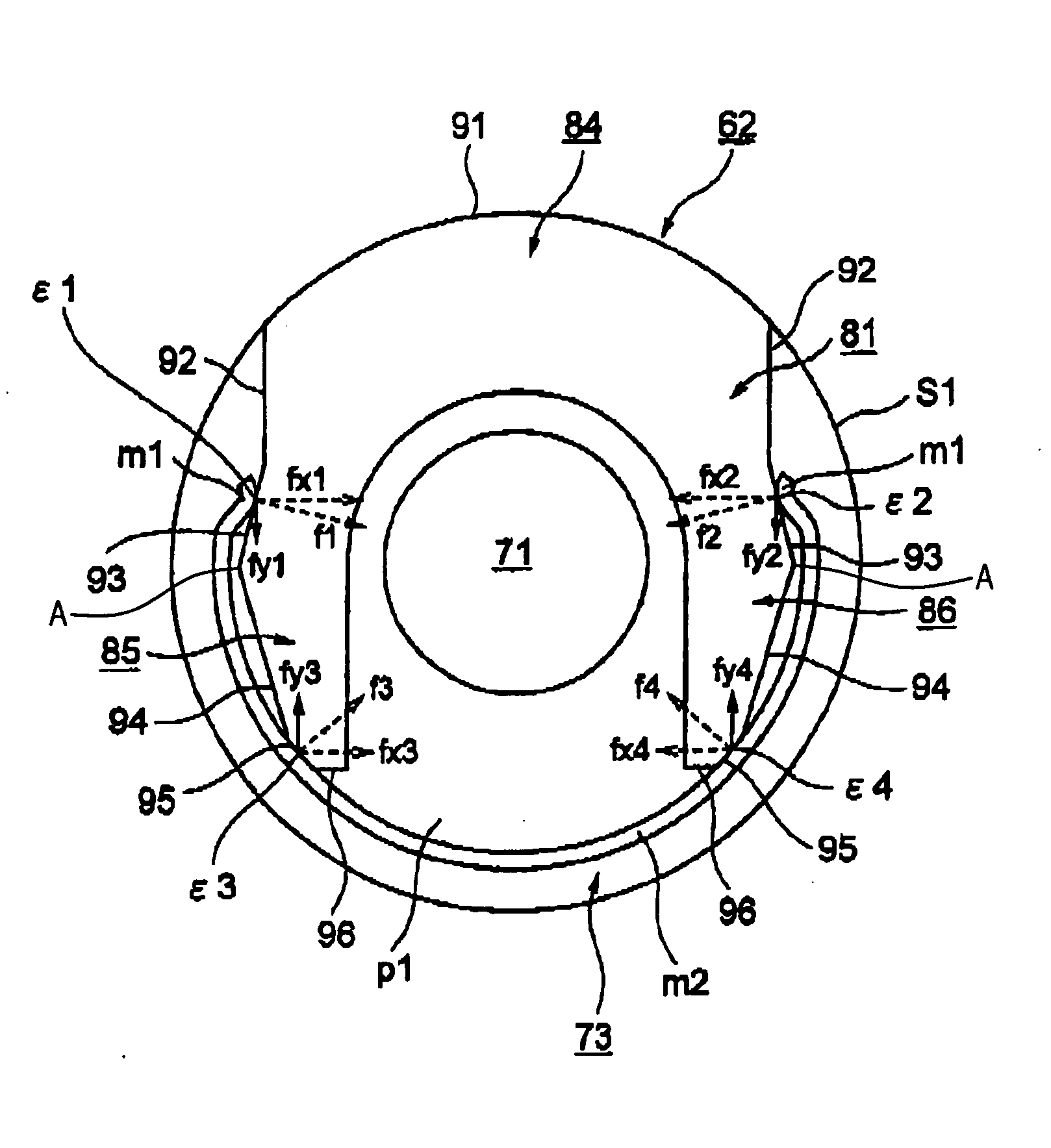
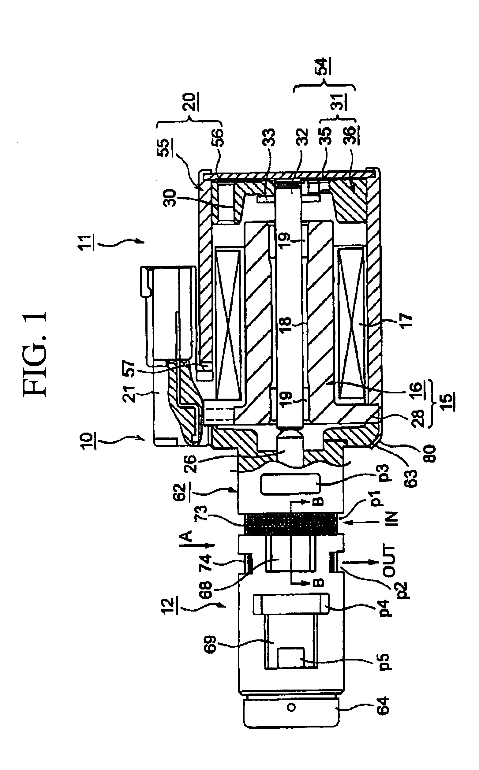
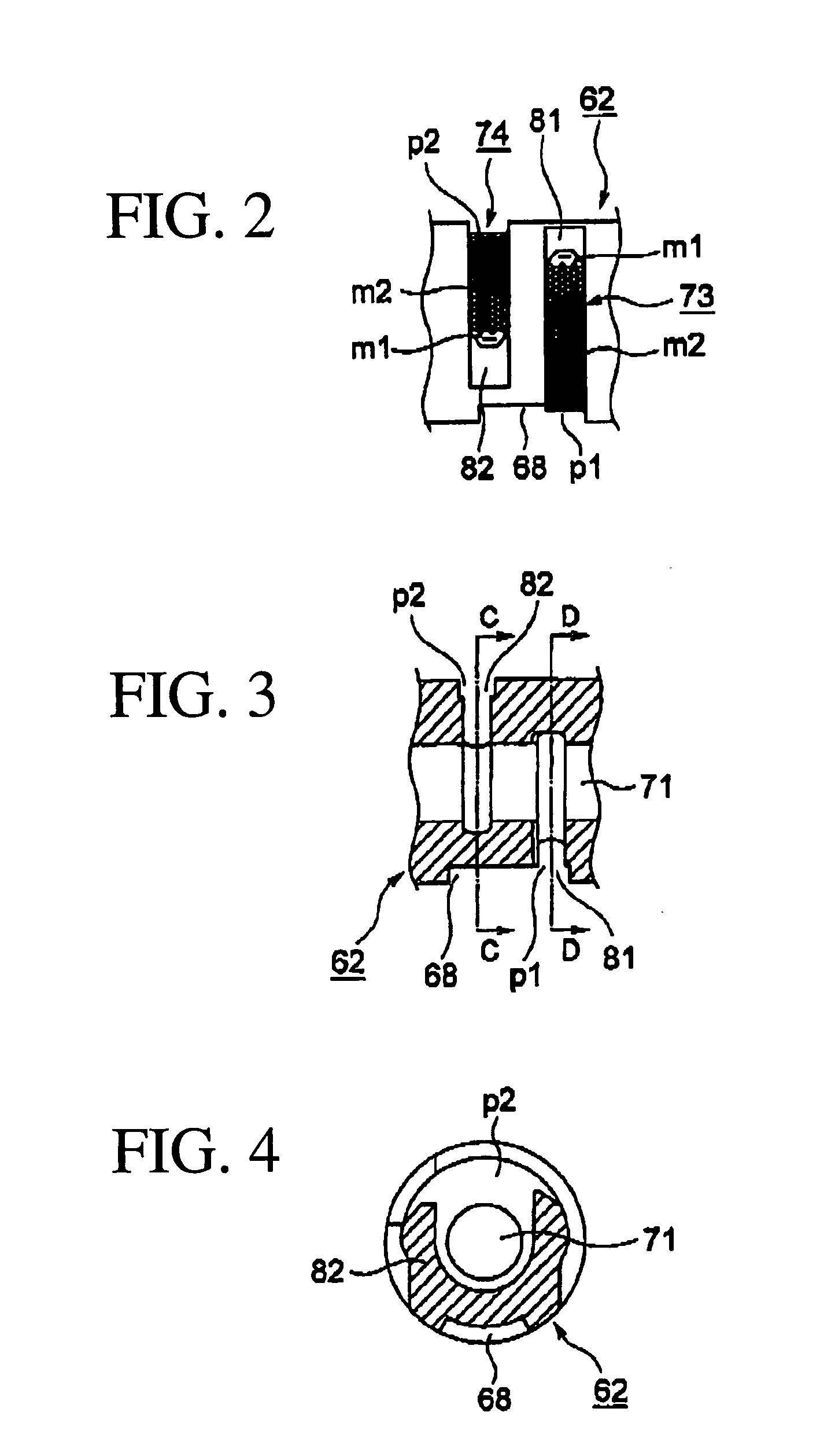
[0032]FIGS. 1-6 show a linear solenoid valve 10 according to the present invention. The linear solenoid valve 10 is connected to a line pressure oil passage or the like in a hydraulic circuit of an automatic transmission via a regulator valve, not shown in the drawing. Oil pressure from an oil pump is regulated by the regulator valve, and this regulated pressure is supplied to the linear solenoid valve 10 as input pressure. The linear solenoid valve 10 is activated by current supplied by a control device, not shown in the drawing, to generate an oil pressure corresponding to the current as a predetermined output pressure (pilot pressure), and to supply the output pressure to a hydraulic servo as control pressure. The hydraulic servo operates to engage and disengage a friction engagement element which is a clutch in this embodiment. The control pressure is supplied to the hydraulic servo according to a predetermined hydraulic pressure pattern for engagement and disengagement of the c...
second embodiment
[0068]In the second embodiment, the coil 17 is formed of a winding 100. A tubular member 101 serves as a first end yoke and is disposed adjacent and radially inward of the coil 17, and extending rearward (toward the right in the drawing) from a predetermined position axially central of the coil 17. An annular end portion 102 serves as a second end yoke and is disposed adjacent the front end (the left end in the drawing) of the coil 17.
[0069]Further, a tubular body 103 including a tubular portion 105 and an annular flange portion 106, formed at the front end of the tubular portion 105 and extending radially outward, with the tubular portion 105 extending within the interior of the coil 17. A plunger 114 is mounted within tubular member 101 and tubular portion 105 for sliding movement left-right in the drawing, radially inward from the end portions 101, 102 and the tubular body 103.
[0070]Next, a third embodiment of the present invention will be described with reference to FIG. 13. Not...
third embodiment
[0071]In this third embodiment, ribs 97, 98 serving as first reinforcement members are formed at a predetermined location on the outer surfaces of respective engagement portions m1. In this embodiment the predetermined location is where the engagement portion curves inward, and the ribs 97, 98 project radially outward. The ribs 97, 98 extend over a predetermined length of the circumferential dimension of the strainer 73, and serve to increase the strength of the engagement portions m1 and thereby prevent deformation of the engagement portions m1. As a result, the retaining force F is increased.
[0072]A second reinforcing rib 99 is formed substantially central of the circumferential dimension of the strainer 73. The rib 99 is formed over a predetermined circumferential length of the strainer 73, and serves to increase the strength of the central part of the strainer 73, thereby preventing the central part of the strainer 73 from deforming such that the contact portions separate from t...
PUM
| Property | Measurement | Unit |
|---|---|---|
| Force | aaaaa | aaaaa |
| Angle | aaaaa | aaaaa |
| Metallic bond | aaaaa | aaaaa |
Abstract
Description
Claims
Application Information
 - R&D
- Intellectual Property
- Life Sciences
- Materials
- Tech Scout
- Unparalleled Data Quality
- Higher Quality Content
- 60% Fewer Hallucinations
Browse by: Latest US Patents, China's latest patents, Technical Efficacy Thesaurus, Application Domain, Technology Topic, Popular Technical Reports.
© 2025 PatSnap. All rights reserved.Legal|Privacy policy|Modern Slavery Act Transparency Statement|Sitemap|About US| Contact US: help@patsnap.com


