
Electronically controlled volume phase grating devices, systems and fabrication methods

a technology of optical devices and phase gratings, which is applied in the field of optical devices and fabrication methods, can solve the problems of low efficiency, poor contrast, and high cost of devices, and achieve the effects of low cost, high efficiency and/or small device form factors

Inactive Publication Date: 2008-09-11
META PLATFORMS TECH LLC
View PDF7 Cites 19 Cited by
  • Summary
  • Abstract
  • Description
  • Claims
  • Application Information

AI Technical Summary

Benefits of technology

The invention provides electrically controlled volume phase gratings and electrically controlled Bragg Gratings that can be used in a transmissive and / or reflective mode. These gratings can be made from electro-optic materials placed directly on glass or semiconductor materials, utilizing conventional LCOS processes and equipment. The invention offers highly efficient and small device form factors, making it ideal for integrated, high resolution imagers that can be up to 2-4 times or more efficient than standard LCOS microdisplays. The invention can be used in integrated micro-projection systems for laptops and gaming devices, front and rear projection HDTV, Heads-up displays, digital art, and many other consumer, commercial, and other applications.

Problems solved by technology

While several emissive display technologies (CRT, LCD, Plasma, etc.) have been the mainstay of the display market, they may be bulky, expensive and / or may not scale well.
While these devices may be low cost because of volume production, they may have poor contrast due to inter-pixel spacing, transistor placement and / or light absorption.
These tubes may be small (perhaps 9-inch diagonal), may be expensive and can be extremely bright.
One of the potential problems with CRT projectors is that, with anywhere from one to three tubes and accompanying lenses and / or a filter wheel built in, the projectors can be quite heavy and large.
Also, CRT devices may not have the fine resolution that LCD devices do, especially when projected.
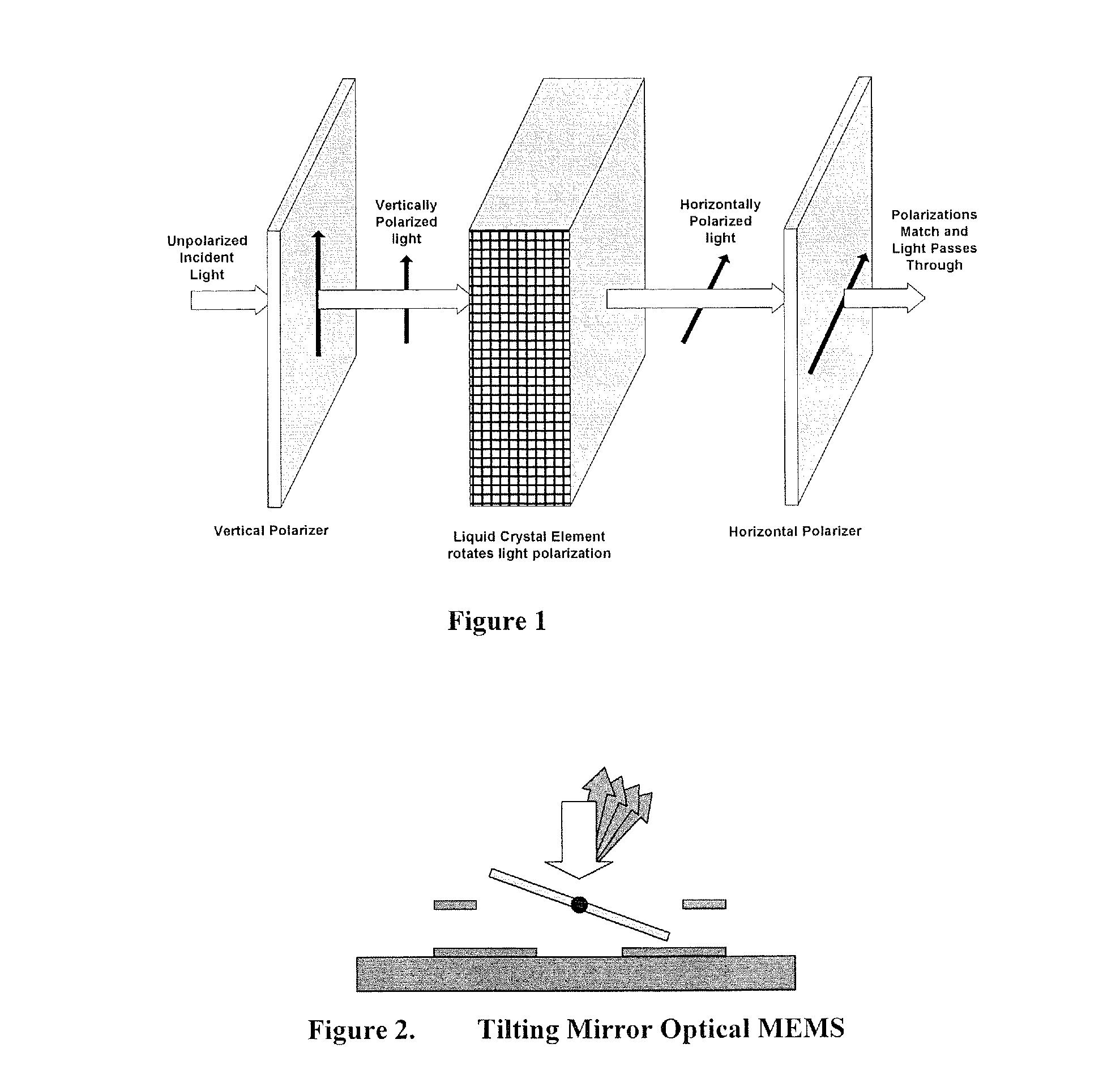
While these may be easier to make than traditional MEMS mirrors, they are still MEMS devices that can have low yields and may be difficult and expensive to make.
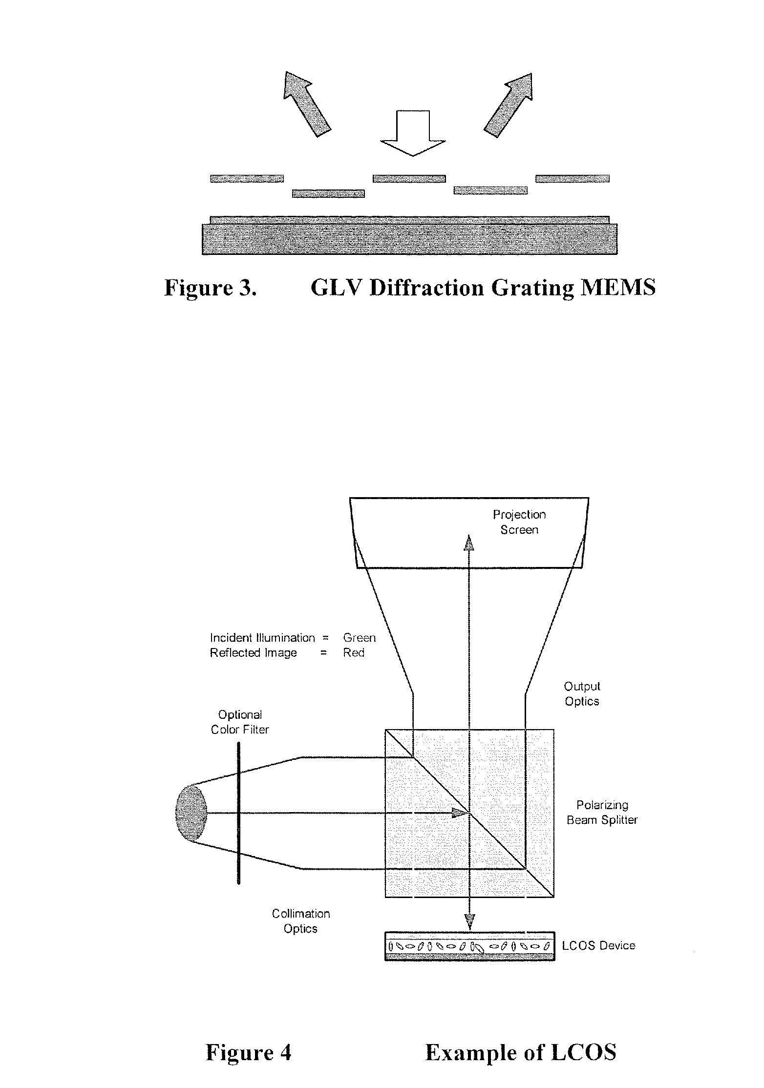
This device may be very inefficient and frequently requires three light valves for imaging Red, Green, and Blue.

Method used


Image

  • Electronically controlled volume phase grating devices, systems and fabrication methods
  • Electronically controlled volume phase grating devices, systems and fabrication methods
  • Electronically controlled volume phase grating devices, systems and fabrication methods

Examples


embodiments

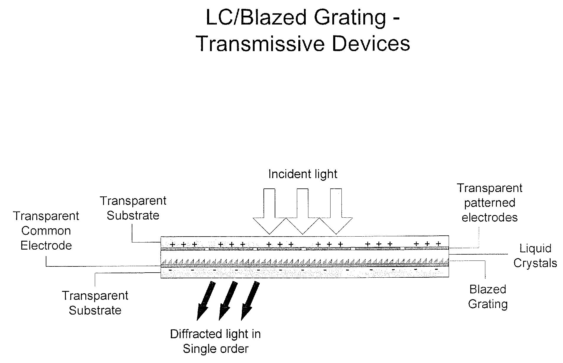
[0084]FIGS. 19A-25A are cross sectional views of electronically controlled volume phase grating devices according to various embodiments of the present invention. These embodiments now will be described in detail. Fabrication technologies and device operation then will be described. In these figures, the plus (+) and minus (−) signs indicate relative voltages. For example, in some embodiments the common electrode is grounded and positive and negative voltages + / −V are applied to the patterned electrodes. Moreover, in these figures, a single electrode, also referred to as a pixilated electrode, spans between about 4 and about 10 grating periods. However, other numbers of grating periods greater than two may be used.

[0085]Referring to FIGS. 19A and 19B, HPDLC-Transmissive Devices are shown. As shown in FIGS. 19A and 19B, Holographically formed PDLC (HPDLC) films are used. HPDLC films are well known to those having skill in the art and the fabrication thereof is well known to those hav...


PUM

PropertyMeasurementUnit
reflectivityaaaaaaaaaa
thicknessaaaaaaaaaa

Abstract

Electrically controlled volume phase gratings and electrically controlled Bragg Gratings can provide variable diffraction gratings that can be operated in a transmissive and / or reflective mode. They can be made from electro-optic materials placed directly on glass or semiconductor materials, utilizing conventional Liquid Crystal on Silicon (LCOS) processes and equipment. Highly efficient and / or small device form factors may be provided.

Description

CROSS-REFERENCE TO RELATED APPLICATION[0001]This application claims the benefit of Provisional Application No. 60 / 558,764, filed Apr. 1, 2004, entitled Electronically Controlled Volume Phase Grating Devices, Systems and Fabrication Methods, the disclosure of which is hereby incorporated herein by reference in its entirety as if set forth fully herein.FIELD OF THE INVENTION[0002]This invention relates to optical devices and fabrication methods therefor, and more specifically to electronically controlled optical devices and fabrication methods therefor.BACKGROUND OF THE INVENTIONProjection Technologies for Microprojection[0003]While several emissive display technologies (CRT, LCD, Plasma, etc.) have been the mainstay of the display market, they may be bulky, expensive and / or may not scale well. Microprojection display technologies also have been developed. Microprojection technologies may fall into two basic types: transmissive and reflective. Transmissive devices may include Liquid C...

Claims


Application Information

Patent Timeline
Patent Type & Authority Applications(United States)
IPC IPC(8): G02B27/44G02B6/00G02F1/1334G02F1/1335
CPCG02F1/13342G02F2201/307G02F1/292G02F1/133504
Inventor KEKAS, JASON
Owner META PLATFORMS TECH LLC
Learn More