
Collapsible steering column assembly

a steering column and assembly technology, applied in the direction of steering columns, steering parts, vehicle components, etc., can solve the problems of preventing the driver from escaping the vehicle, and achieve the effects of reducing maintenance costs, reducing maintenance costs, and reducing maintenance costs

Active Publication Date: 2008-09-11
STEERING SOLUTIONS IP HLDG +1
View PDF4 Cites 13 Cited by
  • Summary
  • Abstract
  • Description
  • Claims
  • Application Information

AI Technical Summary

Benefits of technology

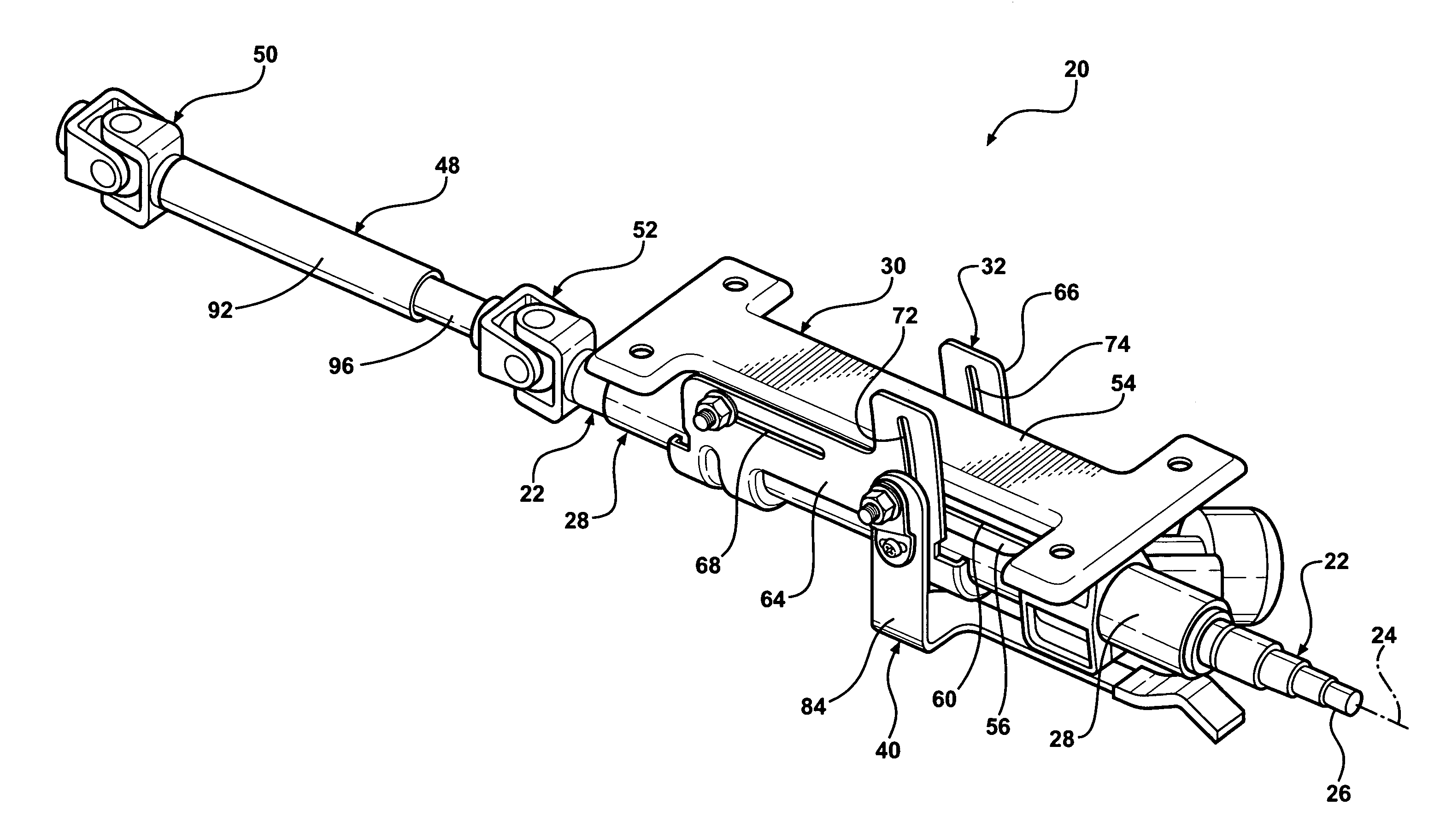
[0008]Preferably, the shuttle has an arcuate slot for receipt of a rake rod that also extends through the first slot of the bracket for the tilt adjustment. A radius of curvature of the arcuate slot is measured from a centerline of the pin. During tilt adjustment, the jacket and steering shaft pivot about a centerline of the pin. During a collision, the pin preferably moves within the second slot and toward the rake rod. This movement misaligns the pivot point or centerline with respect to the curvature of the arcuate slot thus preventing the jacket and steering shaft from falling downward and toward the lap of a driver during a collision.
[0009]Objects, features and advantages of the present invention include an adjustable steering column assembly that remains upwardly supported and away from the driver after a collision. Other advantages include an assembly that is both longitudinally and rake adjustable, and a robust and relatively simple design that is economical to manufacture and requires little or not maintenance.

Problems solved by technology

The mounting bracket and its capsules also provide the means for vertically supporting the end of the column nearest the hand wheel, and upon release of the capsules from the mounting bracket during column collapse, the column assembly and the steering wheel, now no longer vertically supported through the capsules' being secured to the vehicle's structural member, may drop into the driver's lap and impede his extrication from the vehicle after the collision.

Method used


Image

  • Collapsible steering column assembly
  • Collapsible steering column assembly
  • Collapsible steering column assembly

Examples


Embodiment Construction

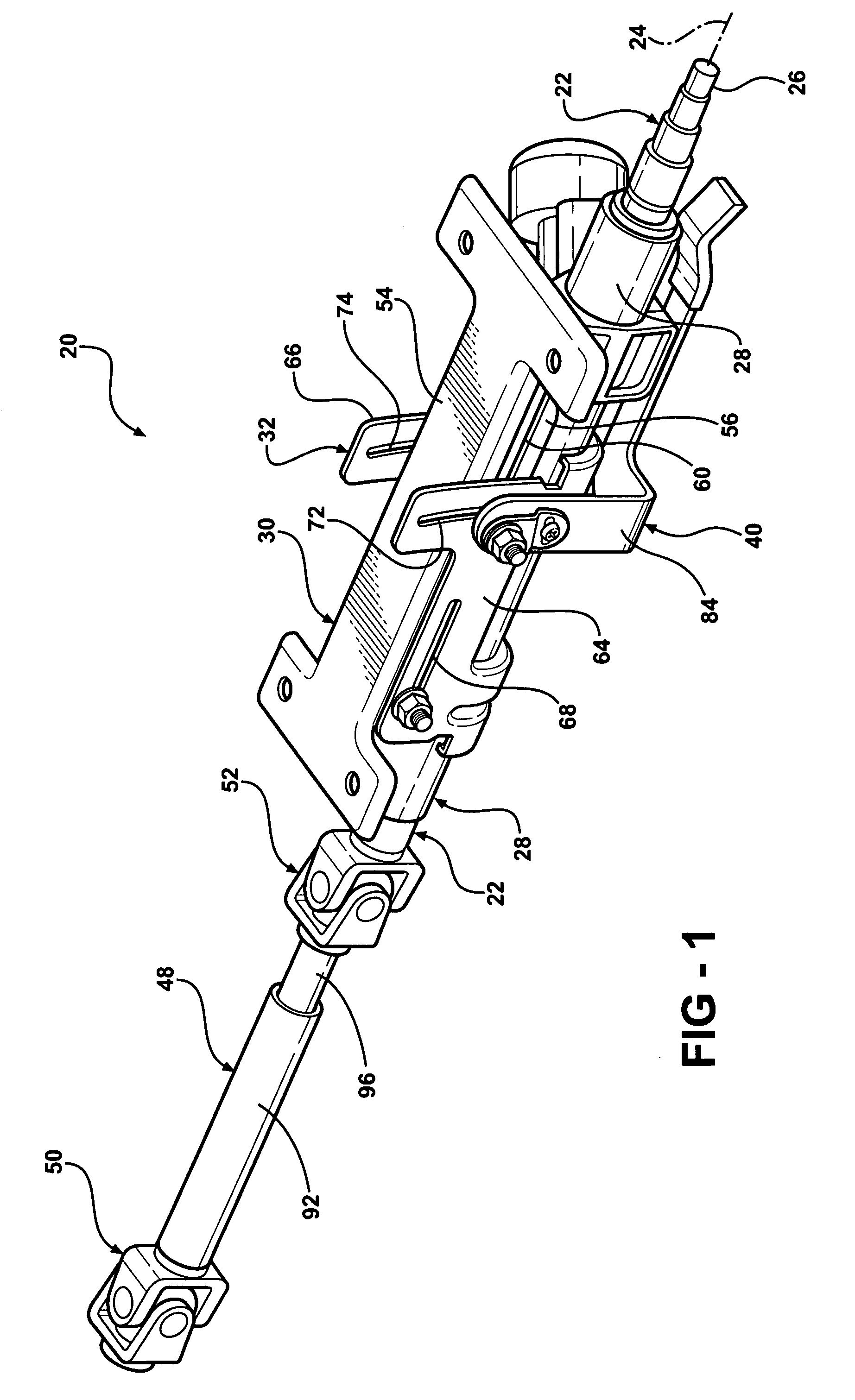
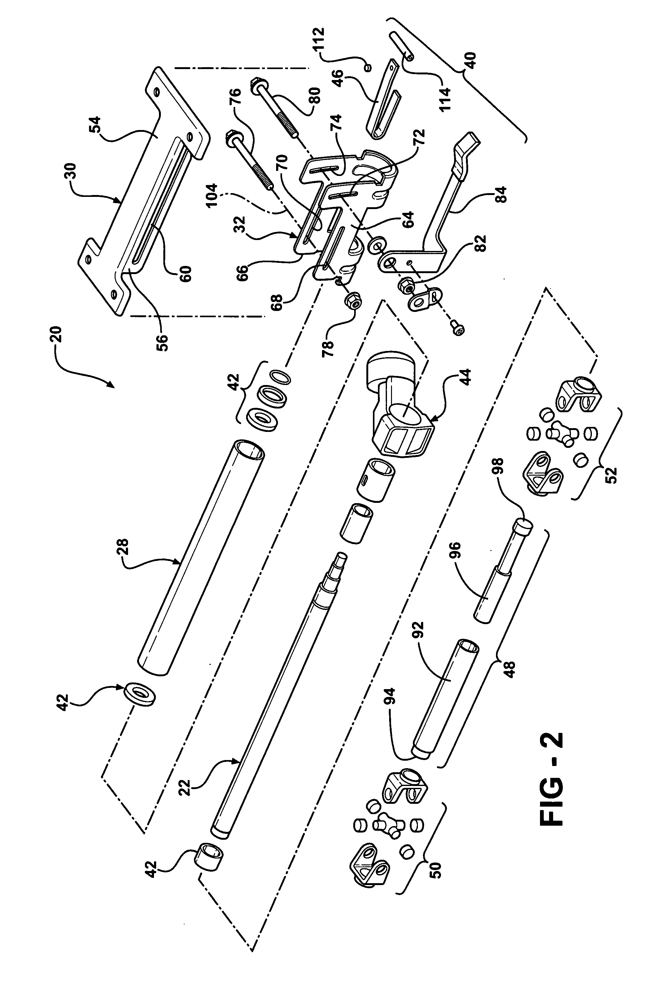
[0020]Referring now to FIGS. 1 and 2 of the drawings, an adjustable steering column assembly 20 for a vehicle has a steering shaft 22 that projects rearward with respect to the vehicle and along a rotation axis 24 to a distal end 26 that attaches to a steering wheel (not shown). The steering shaft 22 is preferably joumaled to and rotates within a tubular housing or jacket 28 engaged rigidly to or generally having a compression bracket or shuttle 32. The shuttle 32 is supported by a bracket 30 of the assembly 20 that engages rigidly to a chassis of the vehicle via a plurality of fasteners (not shown) that project preferably upward from the bracket 30 to engage the chassis.

[0021]The jacket 28 and co-extending shaft 22 are preferably constructed and arranged to extend and retract longitudinally as a single unit and with respect to the bracket 30 between a retracted position 34 (see FIG. 3) and an extended position 36 (see FIG. 4). When extending, the jacket 28 and shaft 22 move in a li...


PUM


Abstract

An adjustable steering column assembly for a vehicle preferably has a bracket for rigid attachment to the vehicle with a first slot defining a longitudinal adjustment path of the assembly. A steering shaft is journaled to a jacket of the assembly for rotation about an axis. A shuttle attaches rigidly to the jacket and adjustably to the bracket for telescoping and tilt adjustment of the assembly. The shuttle has a second slot that defines a collapse path with said second slot preferably having a first portion restraining said steering shaft in a normal state and a second portion that allows said steering shaft to move through said collapse path when in a collapsed state. A pin extends through said first and second slots for coupling said shuttle to said bracket.

Description

RELATED APPLICATIONS[0001]This application claims priority of U.S. Provisional Patent Application Ser. No. 60 / 905,715 filed Mar. 8, 2007, which is incorporated herein by reference.FIELD OF THE INVENTION[0002]This application relates generally to an adjustable steering column assembly for a vehicle, and more particularly to an adjustable steering column that longitudinally collapses during a vehicle crash for the absorption of kinetic energy.BACKGROUND ART[0003]Automotive steering columns are typically equipped with kinetic energy absorption devices to reduce injury of the vehicle operator in event of a collision during which the operator impacts the steering wheel, causing the column to collapse.[0004]Such energy absorbing steering columns generally include a jacket that translates linearly through a collapse stroke during a collision. A force generated by the driver from an impact with the steering wheel initiates the collapse stroke. The steering wheel jacket moves against a resis...

Claims


Application Information

Patent Timeline
Patent Type & Authority Applications(United States)
IPC IPC(8): B62D1/18
CPCB62D1/195B62D1/184
Inventor OLGREN, LELAND N.GREGUS, MICHAEL S.GREGG, JEFF A.NIEDZIELSKI, DONALD A.BOURBINA, ROGER A.
Owner STEERING SOLUTIONS IP HLDG
Learn More