Eureka AIR delivers breakthrough ideas for toughest innovation challenges, trusted by R&D personnel around the world.

Electronic apparatus

Active Publication Date: 2008-09-11
SHARP KK
View PDF19 Cites 33 Cited by
  • Summary
  • Abstract
  • Description
  • Claims
  • Application Information

AI Technical Summary

Benefits of technology

[0009]An object of the present invention is to provide an electronic apparatus which can sufficiently suppress the diffusion of a chemical emission such as a VOC and an odor, and which is less likely to dirty the surroundings of the electronic apparatus such as the outer surface thereof and the walls surrounding the electronic apparatus.
[0012]According to the structure of the first and second electronic apparatuses, the ions generated by the ion generation section react with the chemical emission before the substance is discharged and diffused from the housing in this structure. This enables the efficient removal of the chemical emission from the atmosphere. Thus, the chemical emission such as the VOC and odor is sufficiently suppressed, as compared to the electronic apparatus in Patent Document 1.
[0013]Additionally, at least some of the ions generated by the ion generation section disappear while moving to the outside of the housing. Therefore, the amount of the ion which will react with nitrogen oxide outside the housing is suppressed. Thus, the surroundings of the electronic apparatus such as the outer surface thereof or the walls surrounding the electronic apparatus are less likely to become dirty.
[0014]Moreover, the reaction of the generated ions with the chemical emission occurs mainly within the housing. This prevents inactivated volatile chemical substances inactivated by the reaction from being precipitated outside the housing. Consequently, the re-volatilization of the precipitated chemical emission outside the housing of the electronic apparatus is less likely to occur and harm the human body.
[0015]Furthermore, in the structure of the first electronic apparatus, the electrode member alternately holds positive and negative potentials when an alternative voltage is applied to the electrode member. As a result, positive ions and negative ions generate in the atmosphere around the electrode member. Many of the volatile chemical substances such as the odor and VOC are charged positively; however, there are ones that are negatively charged. This structure enables effective removal of the chemical emission, regardless of whether the chemical emission is charged positively or negatively.

Problems solved by technology

For image forming apparatuses among the electronic apparatuses such as copiers and printers, the peculiar odor which generates from heated paper and toner is also a problem, together with the VOC.
However, there are a few problems with the conventional art as described below.
One is that the distance which the negative ion in air can reach from an ion source is limited, for example if there is no wind then the negative ion can only reach up to 100 mm.
The possibility the negative ion would reach the chemical emission is low due to short distance reach of the negative ion, which makes it difficult to effectively reduce the amount of the chemical emission.
Another is that if the negative ion generator is provided outside the housing of the image forming apparatus, the negative ion reacts with nitrogen oxide (NOx) contained in air around the image forming apparatus, causing nitrogen oxide to precipitate outside the housing.
This may cause the dirtying of a paper output tray or the housing of the image forming apparatus, or even the wall, floor or the like of the room the image forming apparatus is placed, due to the precipitated nitrogen oxide adhering therewith.
If the ion generator is provided outside the housing of the image forming apparatus as in Patent Document 1, the once-precipitated VOC may again volatilize (secondary generation), and cause harm.

Method used


Image

  • Electronic apparatus
  • Electronic apparatus
  • Electronic apparatus

Examples


first embodiment

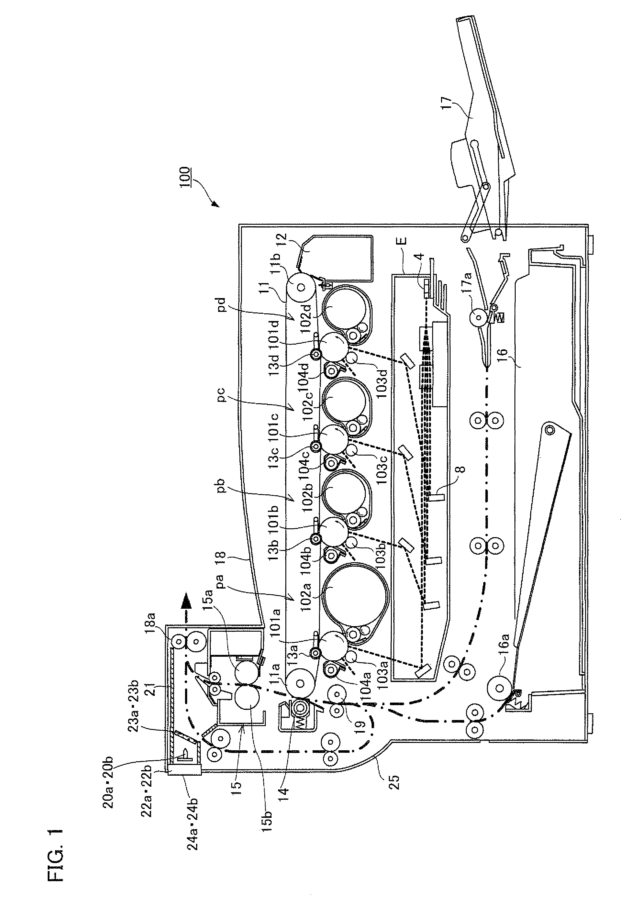
[0048]The first embodiment of the present invention is described as below with reference to FIGS. 1 through 9. The present embodiment explains an example applying the present invention to a color multifunction apparatus. FIG. 1 illustrates one embodiment of the present invention, and is a longitudinal sectional view of a brief structure of a color multifunction apparatus 100.

[0049]The color multifunction apparatus 100 is an electrophotographic image forming apparatus. Multicolor or monochrome images are formed on a sheet (recording medium, printing paper) based on a print job data inputted from a personal computer or the like not illustrated. The color multifunction apparatus 100 includes an optical unit E, four visible image formation units pa, pb, pc and pd, an intermediate transfer belt 11, a secondary transfer unit 14, a fixing unit 15, and an inner paper feeding unit 16, which are an image formation section which forms an image on a sheet, a housing 25 containing the image form...

experiment 1

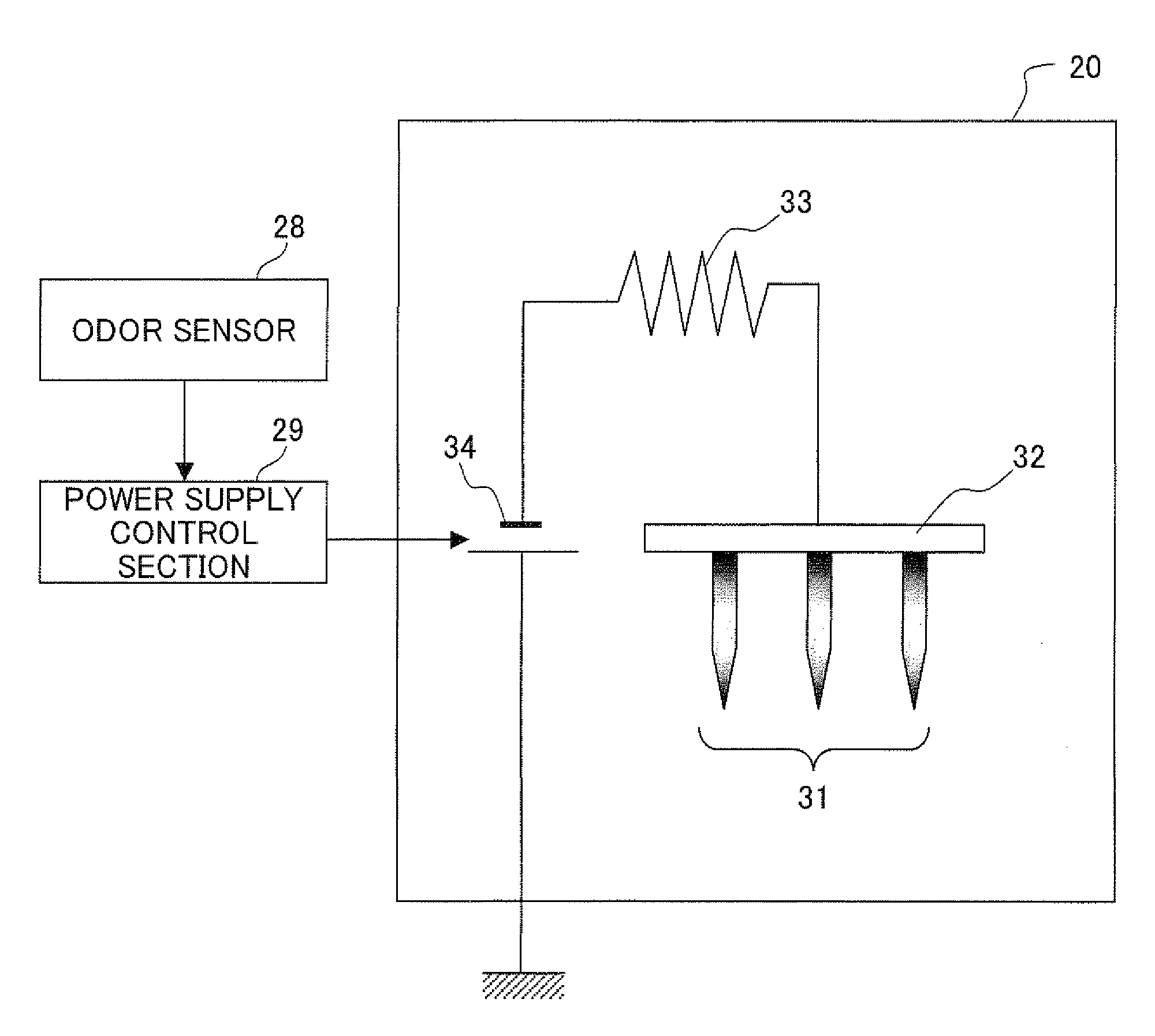
[0073]A relationship between a distance from the central ionization needle 31 and a concentration of the negative ion was studied, using the ion generator 20. In details, the concentration of the negative ion in an atmosphere was measured while changing the distance from the ionization needles 31, under the state where: (i) the ion generator 20 was positioned in a space with nothing surrounding within 1 m in all directions, (ii) the base frame 32 was connected to the high voltage power supply 34, and (iii) a voltage of −5 kV was applied to the ionization needles 31.

[0074]A MODEL 610C manufactured by Trek Incorporated was used for the high voltage power supply 34, and an AIC-2000 manufactured by Sato Shoji Corporation was used as a negative ion counter. The negative ion counter was arranged such that the air suction opening thereof was positioned 5 to 150 mm away from the needlepoint of the ionization needles 31 and the number of negative ions (number included in an air of a given ca...

experiment 2

[0078]Next, the effect of reducing the VOC or odor by the negative ions generated from the ion generator 20 was studied. The present experiment uses a color laser printer CX-400 manufactured by Ricoh Company, Ltd. instead of the color multifunction apparatus 100, arranging the ion generator 20 in the space above a fixing unit inside the housing thereof. The odor and TVOC (total Volatile Organic Compounds) was measured in the vicinity of the paper output opening after continuous printing with the CX-400. This measurement was repetitively conducted while changing the voltage being applied to the ionization needles 31 of the ion generator 20, in a range of 0 V to −3.5 kV. A total of 100 color copies were printed in the continuous printing, with a print rate of 20% (5% per color) at a speed of 25 sheets per minute. An XP-329111 manufactured by New Cosmos Electric Co., Ltd was used as an odor measuring device, and an HV-1000 manufactured by JMS was used as a TVOC measuring device. The me...


PUM


Abstract

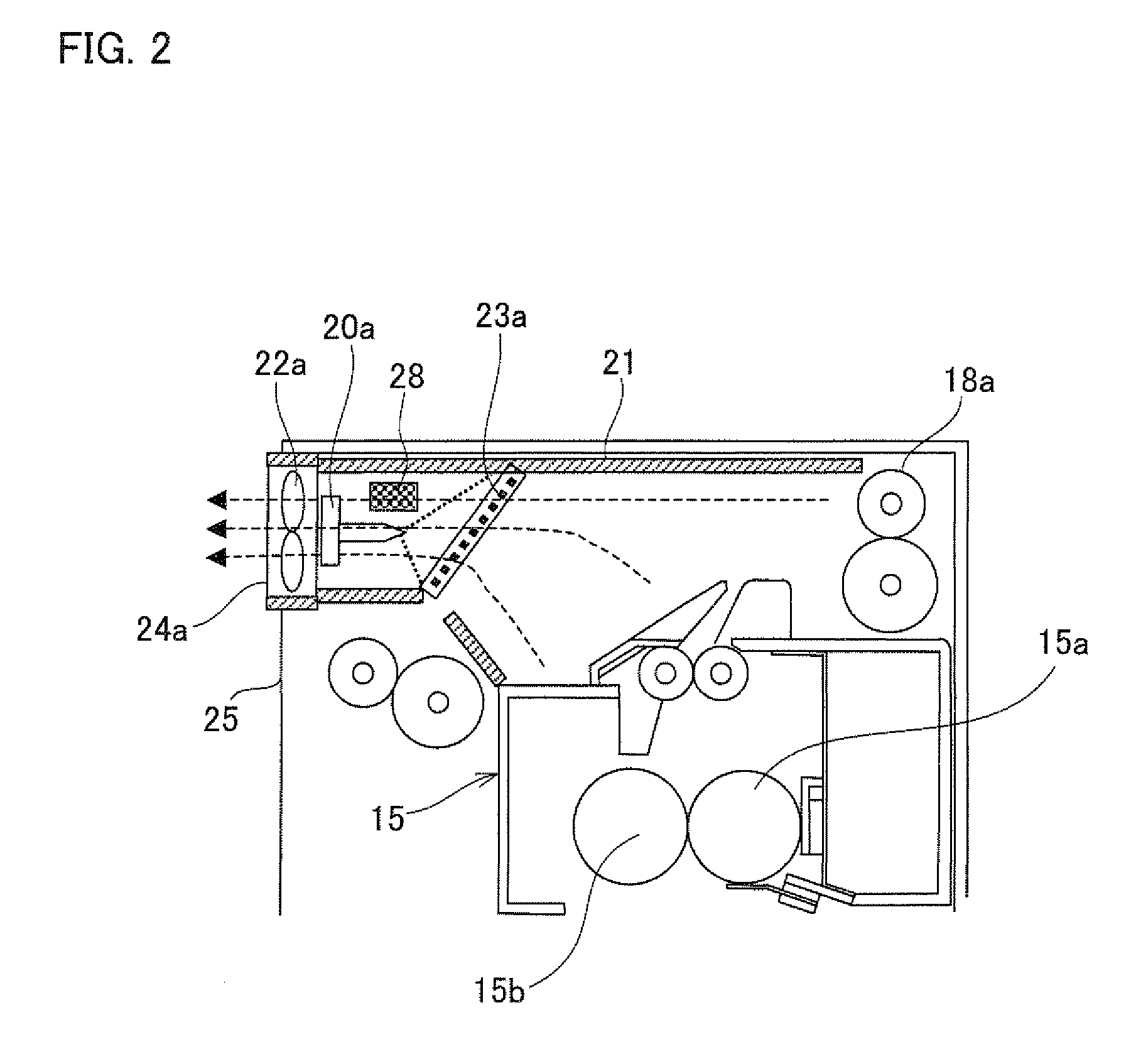
An electronic apparatus of the present invention includes an ion generator which generates ions in an atmosphere to remove chemical emission such as VOC and odor. The ion generator is arranged inside the duct which leads the chemical emission generated from the fixing unit to the discharge opening, and also generates positive ions and negative ions in the atmosphere, thereby can efficiently remove the chemical emission. With this arrangement, an electronic apparatus is realized which sufficiently suppresses the chemical emission such as VOC and odor, and is less likely to dirty the surroundings of the electronic apparatus such as the outer surface thereof and the walls surrounding the electronic apparatus.

Description

[0001]This Nonprovisional application claims priority under 35 U.S.C. § 119(a) on Patent Applications No. 057871 / 2007 filed in Japan on Mar. 7, 2007 and No. 161907 / 2007 filed in Japan on Jun. 19, 2007, the entire contents of which are hereby incorporated by reference.FIELD OF THE INVENTION[0002]The present invention relates to an electronic apparatus (for example personal computers, copiers, printers and the like) which generates chemical emission such as an odor or a VOC (Volatile Organic Compounds). More particularly, the present invention relates to an electronic apparatus provided with an ion generation section to reduce the amount of the chemical emission.BACKGROUND OF THE INVENTION[0003]Recently, VOC is recognized as one causative agent for so-called sick house syndrome, which causes pollution related health damage such as headaches and dizziness. It is found that this VOC is emitted from electronic apparatuses such as personal computers, copier, printers and the like. For ima...

Claims


Application Information

Patent Timeline
IPC IPC(8): H01J27/00
CPCH01J27/02A61L9/22
Inventor KAGAWA, TOSHIAKIDOSHOHDA, HIROSHI
Owner SHARP KK
Why Eureka
Eureka Blog
Learn More