
Bipolar Resistive Memory Device Having Tunneling Layer

a resistance memory and bipolar technology, applied in resistor details, digital storage, diodes, etc., can solve the problems of low degree of integration, poor fatigue characteristic, and loss of stored data,

Inactive Publication Date: 2008-09-04
SAMSUNG ELECTRONICS CO LTD
View PDF7 Cites 57 Cited by
  • Summary
  • Abstract
  • Description
  • Claims
  • Application Information

AI Technical Summary

Benefits of technology

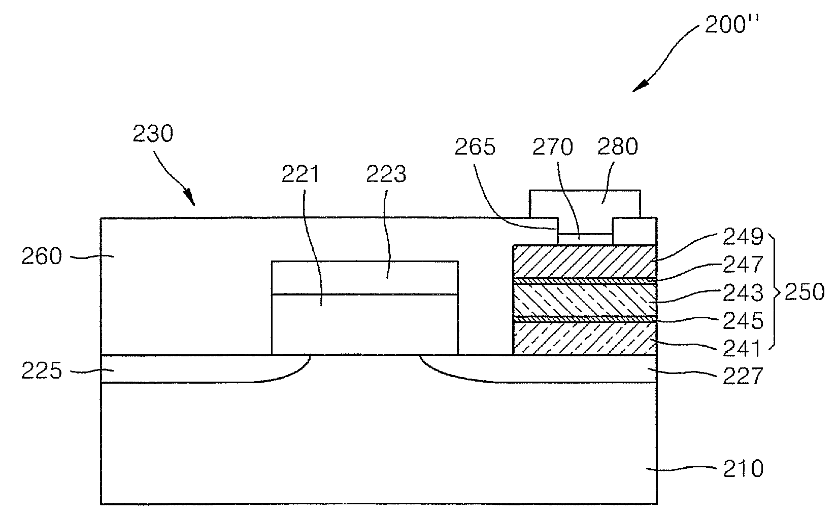
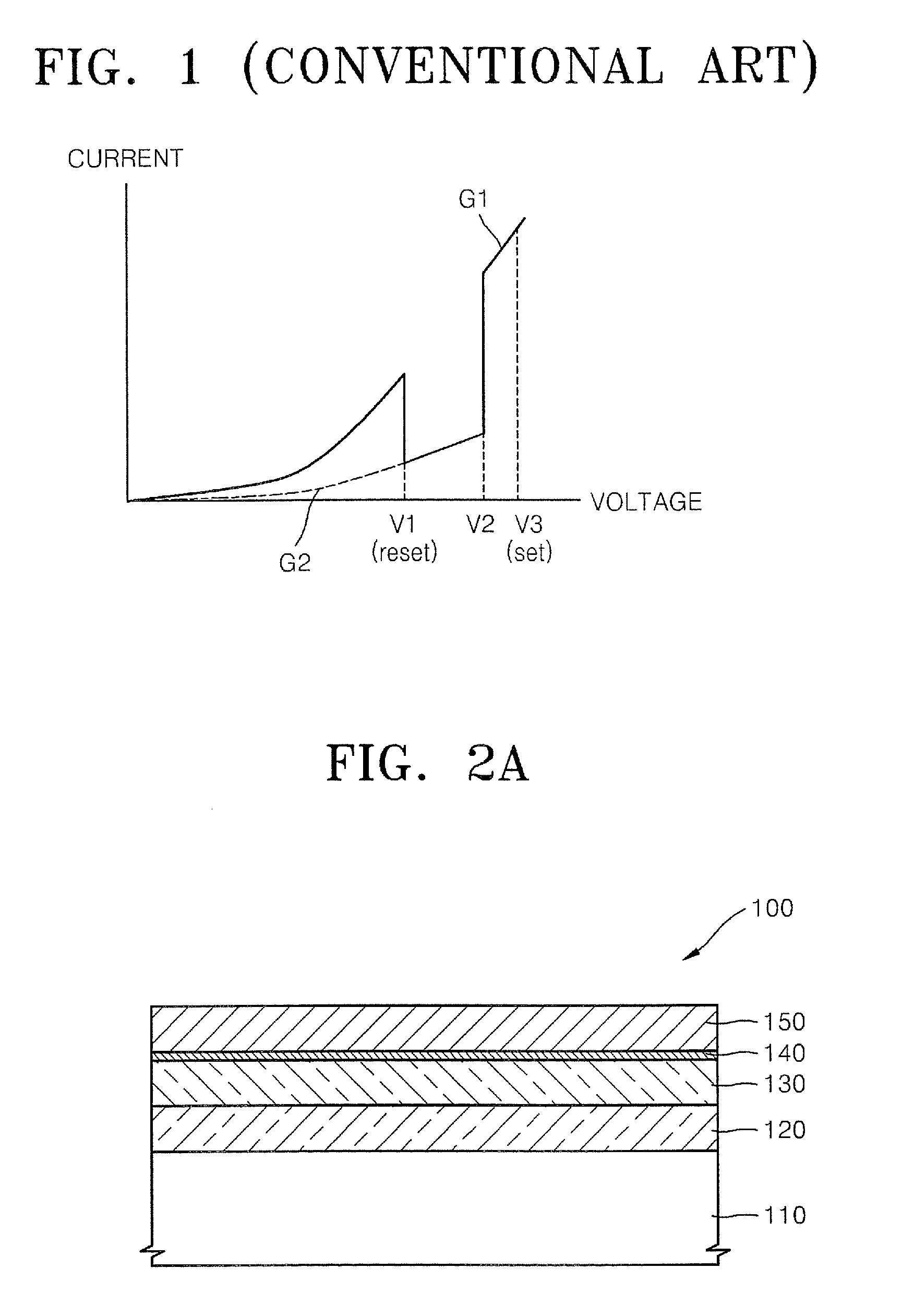
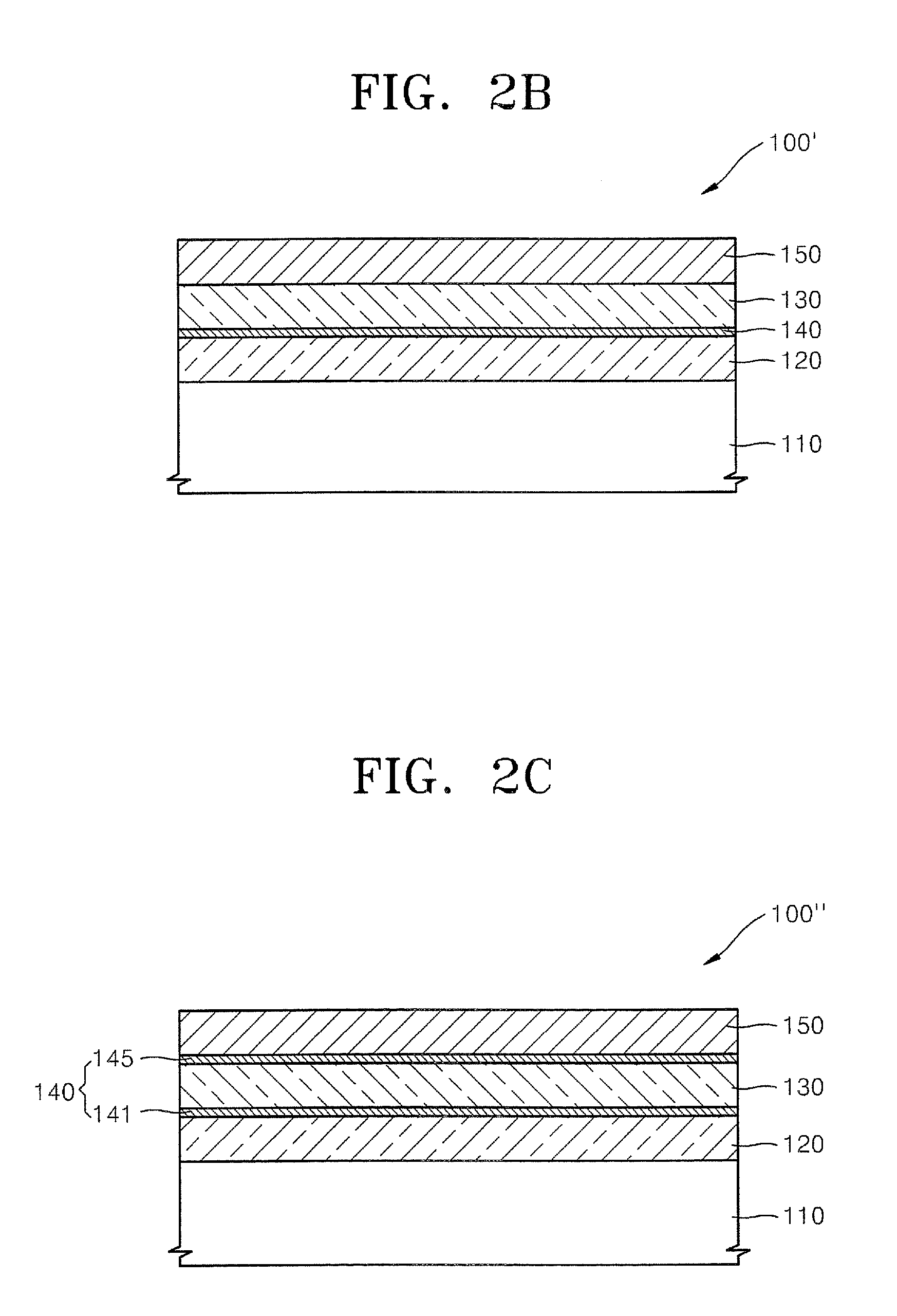
[0010]In some embodiments of the present invention, a nonvolatile memory device includes a semiconductor substrate, a first electrode on the semiconductor substrate, a resistive layer on the first electrode, a second electrode on the resistive layer and at least one tunneling layer interposed between the resistive layer and the first electrode and/or the second electrode. The resistive layer and the tunneling layer may support transition between first and second resistance states responsive to first and second voltages applied across the first and second electrodes. The first and second voltages may have opposite polarities.
[0011]In some embodiments, the resistive layer may include a transition metal oxide film and the tunneling layer may include a metal oxide film. For example, the resistive layer may include NiO, TiO2, ZrO2, HfO2, WO3, CoO or Nb2O5, and the tunneling layer may include MgO, AlOx or ZnO. In some embodiments, the resistive layer may have a thickness in a range from about 40 Å to about 1000 Å, more particularly, a ...

Problems solved by technology

However, volatile memory typically has the disadvantage that, if power is turned off, stored data is lost.
In contrast, nonvolatile memory devices typically retain data when the power is turned off, but may offer a lower degree of integration and a slow operating speed compared to DRAM or other types of volatile memory.
In conventional resistive memory devices with a unipolar switching operating characteristic, a fatigue characteristic may be poor.
This may lower the reliability of the device.
Operating current may also be high, and operating speed may be limited.

Method used


Image

  • Bipolar Resistive Memory Device Having Tunneling Layer
  • Bipolar Resistive Memory Device Having Tunneling Layer
  • Bipolar Resistive Memory Device Having Tunneling Layer

Examples


Embodiment Construction

[0019]The invention is described more fully hereinafter with reference to the accompanying drawings, in which embodiments of the invention are shown. This invention may, however, be embodied in many different forms and should not be construed as limited to the embodiments set forth herein. Rather, these embodiments are provided so that this disclosure will be thorough and complete, and will fully convey the scope of the invention to those skilled in the art.

[0020]It will be understood that when an element or layer is referred to as being “on,”“connected to” and / or “coupled to” another element or layer, the element or layer may be directly on, connected and / or coupled to the other element or layer, or intervening elements or layers may be present. In contrast, when an element is referred to as being “directly on”, “directly connected to” and / or “directly coupled to” another element or layer, no intervening elements or layers are present. As used herein, the term “and / or” includes any...


PUM


Abstract

A nonvolatile memory device includes a semiconductor substrate, a first electrode on the semiconductor substrate, a resistive layer on the first electrode, a second electrode on the resistive layer and at least one tunneling layer interposed between the resistive layer and the first electrode and / or the second electrode. The resistive layer and the tunneling layer may support transition between first and second resistance states responsive to first and second voltages applied across the first and second electrodes. The first and second voltages may have opposite polarities.

Description

CROSS-REFERENCE TO RELATED PATENT APPLICATION[0001]This application claims the benefit of Korean Patent Application No. 10-2007-0021170, filed on Mar. 2, 2007, in the Korean Intellectual Property Office, the disclosure of which is incorporated herein in its entirety by reference.FIELD OF THE INVENTION[0002]The present invention relates to nonvolatile memory devices and, more particularly, to a resistor memory devices.BACKGROUND OF THE INVENTION[0003]Memory devices include volatile memory devices, like DRAM (dynamic random access memory), in which if power is turned off, data stored in a memory cell is lost, and nonvolatile memory devices, in which data is maintained even after power is turned off. Nonvolatile memory devices include MRAM (magnetic random access memory), FRAM (ferroelectric random access memory), PRAM (phase-change random access memory), and RRAM (resistor random access memory). Volatile memory devices often have a capability for a high degree of integration and high ...

Claims


Application Information

Patent Timeline
IPC IPC(8): H01L29/8605H01C1/012
CPCH01L27/112H01L27/115H01L45/08H01L27/2436H01L45/1233H01L45/146H01L45/12H10B63/30H10N70/801H10N70/24H10N70/826H10N70/8833H10B20/00H10B69/00G11C13/0004H01L27/11801
Inventor ZHAO, JIN SHILEE, JANG-EUNBAEK, IN-GYUOH, SE-CHUNGNAM, KYUNG-TAEYIM, EUN-KYUNG
Owner SAMSUNG ELECTRONICS CO LTD
Learn More