
Motor rotor and method for manufacturing same

A motor rotor and rotor technology, which is applied in the manufacture of stator/rotor body, magnetic circuit rotating parts, magnetic circuit shape/style/structure, etc. It can solve the problem of insufficient sealing of magnetic poles, corrosion and pulverization of magnetic poles, and reduce the power generation of wind turbines etc. to achieve the effect of reducing manufacturing man-hours, reducing cogging torque and torque ripple

Active Publication Date: 2019-09-06
BEIJING GOLDWIND SCI & CREATION WINDPOWER EQUIP CO LTD
View PDF15 Cites 0 Cited by
  • Summary
  • Abstract
  • Description
  • Claims
  • Application Information

AI Technical Summary

Problems solved by technology

Although the plug-in magnetic pole fixing process realizes the reliable fixing of the magnetic pole through the slot fixed structure, there is still a hidden danger of insufficient sealing of the magnetic pole. Under the long-term high temperature and high humidity operating conditions of the wind turbine, the magnetic pole is extremely prone to corrosion. Powdering, thereby weakening the excitation flux of the rotor pole and the air gap magnetic induction of the generator, thereby reducing the power generation of the wind turbine

Method used


Image

  • Motor rotor and method for manufacturing same
  • Motor rotor and method for manufacturing same
  • Motor rotor and method for manufacturing same

Examples


Embodiment Construction

[0042] In order to enable those skilled in the art to better understand the technical concept of the present invention, specific embodiments of the present invention will be described in detail below in conjunction with the accompanying drawings. In the accompanying drawings, the same reference numerals always represent the same components.

[0043] "Axial" mentioned in this article refers to the axial direction parallel to the central rotation axis of the motor rotor, "circumferential" refers to the circumferential direction along the rotor rotation direction, and "radial" refers to the radial direction of the motor .

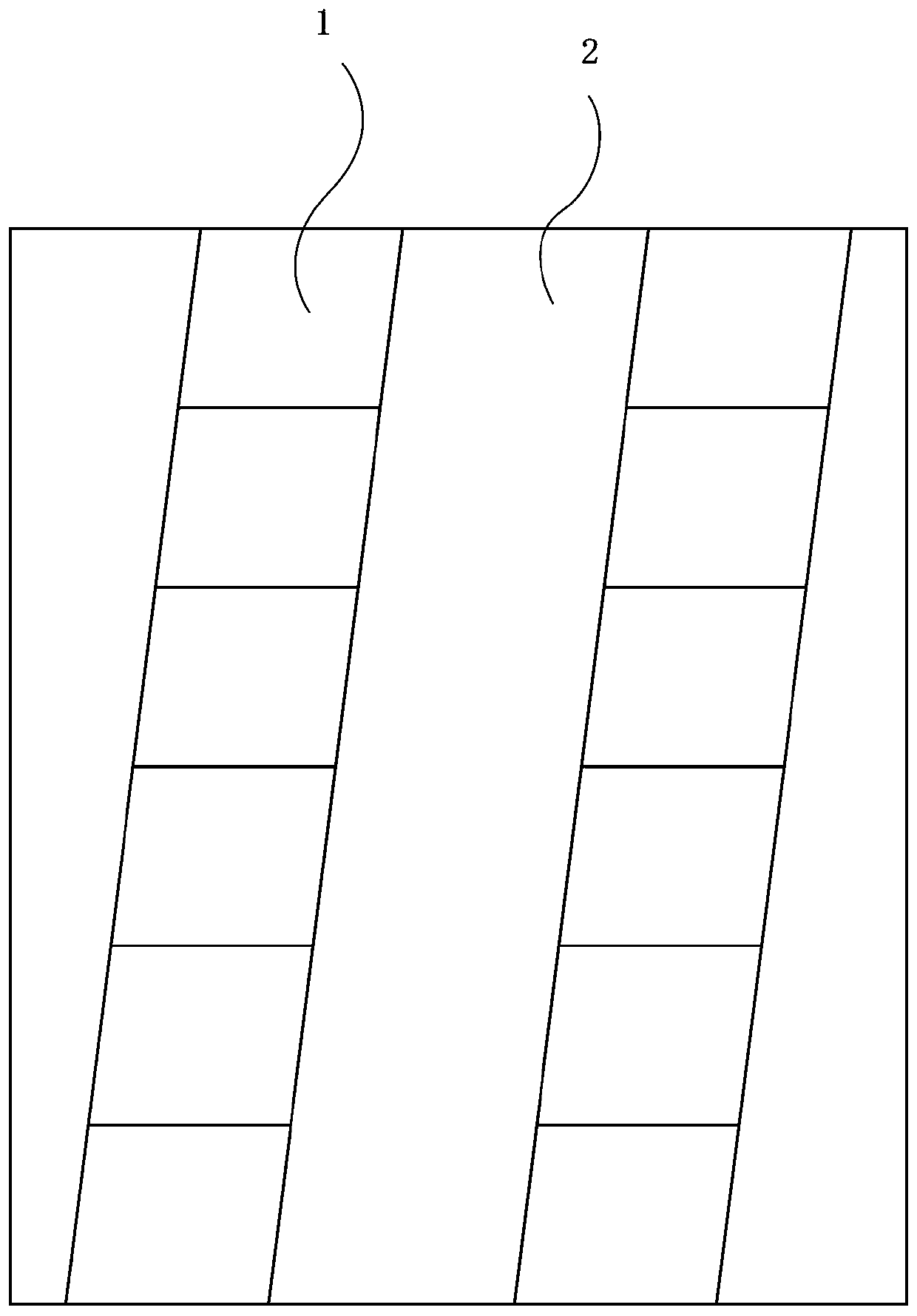
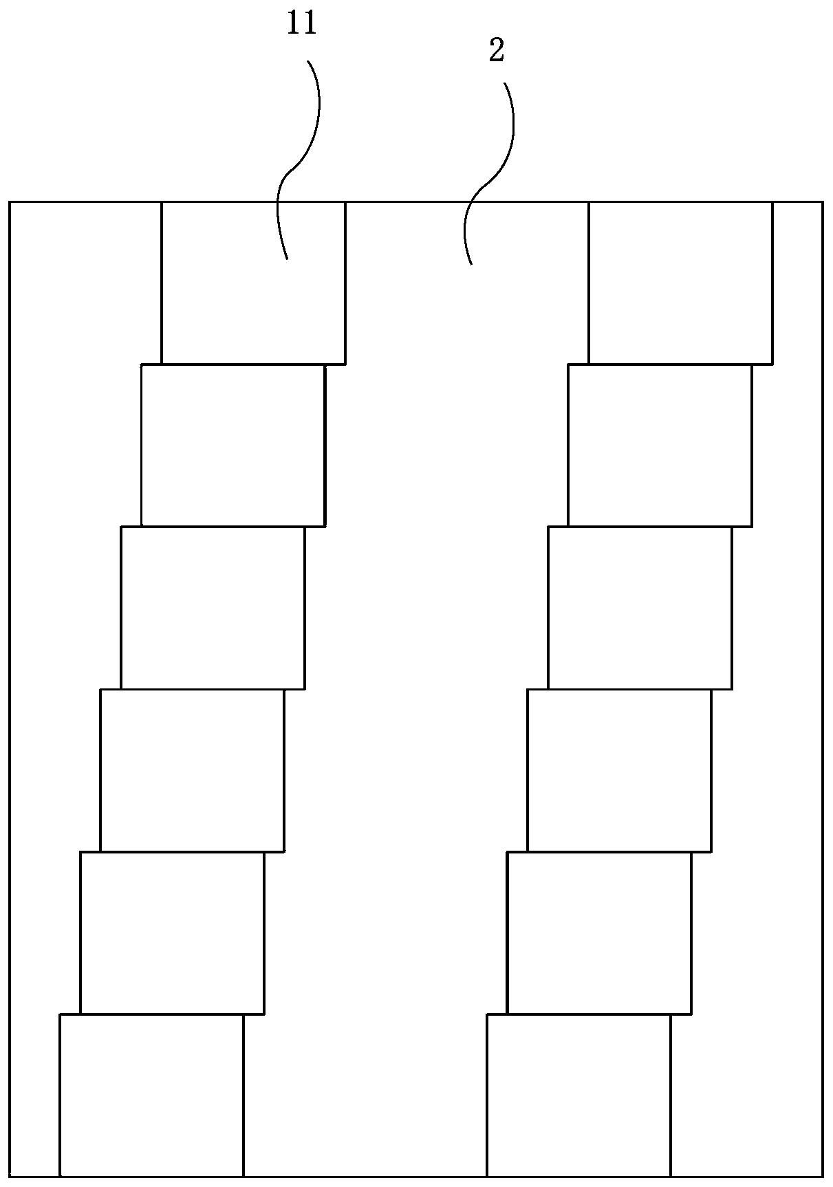
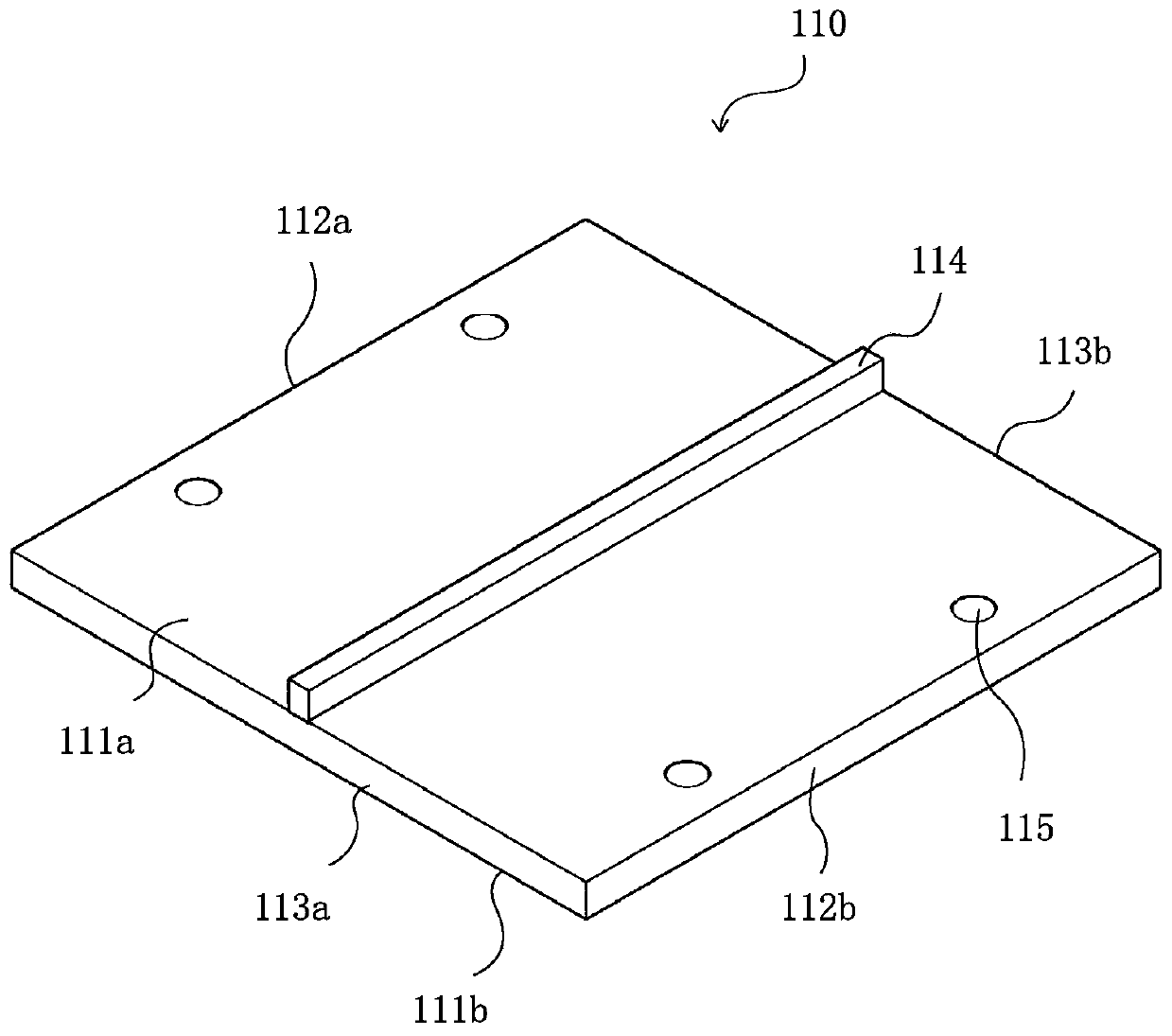
[0044] Figure 3 to Figure 9 A pole module 100 according to a first embodiment of the present invention and a motor rotor 1000 including the pole module 100 are shown. refer to Figure 3 to Figure 8 In other words, the pole module 100 may mainly include a base plate 110 , a pair of pole units (a first pole unit 120 and a second pole unit 130 ), and a case 14...


PUM


Abstract

The invention relates to a motor rotor and a method of manufacturing the same. The motor rotor (2000) includes a rotor yoke (250) and a plurality of magnetic pole modules (200) disposed on the rotor yoke (250); each magnetic pole module (200) includes a substrate (210), a case (240) and a pair of magnetic pole units (220, 230) with opposite polarities accommodated in an accommodation space formedby the substrate (210) and the case (240); the magnetic pole units (220, 230) in each magnetic pole module (200) are spaced apart from each other by a first distance along the circumferential direction of the rotor yoke (250); and the plurality of magnetic pole modules (200) are mechanically fixed to the rotor yoke (250) through pressing bars (280) and fasteners ( 270). With the motor rotor of themotor rotor of the invention, generator performance (cogging torque and torque ripple), the protection of the magnetic poles, and the mechanical fixation of the magnetic poles can be shared.

Description

technical field [0001] The present invention relates to the field of electrical machines, and more specifically, to a magnetic pole module, a motor rotor including the magnetic pole module, and a method for manufacturing the motor rotor. Background technique [0002] For permanent magnet direct drive generators of large wind turbines, two important design indicators are to reduce the cogging torque and torque ripple of the generator. The smaller the cogging torque of the generator, the lower the cut-in wind speed of the wind turbine unit, which expands the operating range of the unit's speed and improves the utilization rate of wind energy and the power generation of the unit. The smaller the torque ripple of the generator, the higher the operation stability of the wind turbine and the longer the service life of the rotating parts such as bearings. [0003] In order to reduce the cogging torque and torque ripple of the generator, the usual solution in motor design is that t...

Claims


Application Information

Patent Timeline
Patent Type & Authority Patents(China)
IPC IPC(8): H02K1/27H02K15/03
Inventor 孙杨宋佺
Owner BEIJING GOLDWIND SCI & CREATION WINDPOWER EQUIP CO LTD
Learn More