
Processor and compiler for decoding an instruction and executing the instruction with conditional execution flags

a compiler and instruction technology, applied in the field of processors and compilers, can solve problems such as large-scale circuits, and achieve the effect of high speed and low power consumption

Inactive Publication Date: 2008-08-28
OKABAYASHI HAZUKI +3
View PDF9 Cites 8 Cited by
  • Summary
  • Abstract
  • Description
  • Claims
  • Application Information

AI Technical Summary

Benefits of technology

"The present invention provides a processor and a compiler that can efficiently decode and execute loop instructions, while consuming a small amount of power and reducing the circuitry size. The processor uses a flag register to determine whether the loop has reached the end of the execution phase, based on a conditional execution flag. The flag register stores a plurality of conditional execution flags, which are used as predicates for conditional execution instructions. The decoding unit decodes the loop instruction and the execution unit executes it. The processor can also store a loop flag in the flag register, which is used to determine whether the loop has reached the end of the execution phase. The processor and the compiler use a flag register to determine whether the loop has reached the end of the execution phase, which helps to prevent the circuitry size from becoming large and consuming a large amount of power. This reduces the power consumption of the processor and improves its performance."

Problems solved by technology

Therefore, such processor is required to be equipped with many resources, which results in large-scale circuits.

Method used


Image

  • Processor and compiler for decoding an instruction and executing the instruction with conditional execution flags
  • Processor and compiler for decoding an instruction and executing the instruction with conditional execution flags
  • Processor and compiler for decoding an instruction and executing the instruction with conditional execution flags

Examples


example 1

[0104]mov r1, 0x23;;

[0105]This instruction description indicates that only an instruction “mov” shall be executed.

example 2

[0106]mov r1, 0x38

[0107]add r0, r1, r2

[0108]sub r3, r1, r2;;

[0109]These instruction descriptions indicate that three instructions of “mov”, “add” and “sub” shall be executed in parallel.

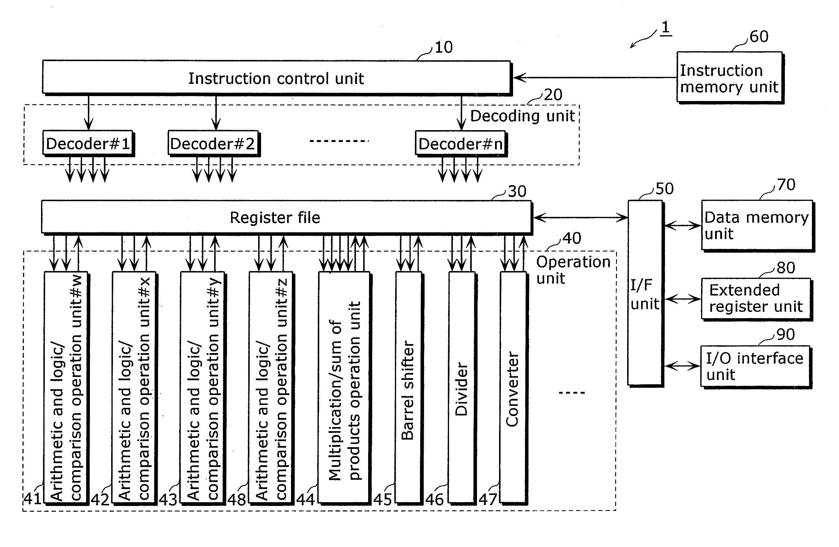
[0110]The instruction control unit 10 identifies an issue group and sends the identified issue group to the decoding unit 20. The decoding unit 20 decodes the instructions in the issue group, and controls resources required for executing such instructions.

[0111]Next, an explanation is given for registers included in the processor 1.

[0112]Table 1 below lists a set of registers of the processor 1.

TABLE 1Register nameBit widthNo. of registersUsageR0-R3132 bits32General-purpose registers. Used as datamemory pointer, data storage at the time ofoperation instruction, and the like.TAR32 bits1Branch register. Used as branch addressstorage at branch point.LR32 bits1Link register.SVR16 bits2Save register. Used for saving conditional flag(CFR) and various modes.M0-M164 bits2Operation registers. Used as data sto...


PUM


Abstract

The present invention provides a processor which has a small-scale circuit and is capable of executing loop processing at a high speed while consuming a small amount of power. When the processor decodes an instruction “jloop C6,C1:C4,TAR,Ra”, the processor (i) sets a conditional flag C4 to 0 when the value of a register Ra is smaller than 0, (ii) moves the value of a conditional flag C2 to a conditional flag C1, moves the value of a conditional flag C3 to the conditional flag C2, and moves the value of the conditional flag C4 to the conditional flags C3 and C6, (iii) adds −1 to the register Ra and stores the result into the register Ra, and (iv) branches to an address specified by a branch register (TAR). When not filled with a branch target instruction, the jump buffer will be filled with a branch target instruction.

Description

[0001]This is a Rule 1.53(b) Divisional of Ser. No. 10 / 805,381, filed Mar. 22, 2004BACKGROUND OF THE INVENTION[0002](1) Field of the Invention[0003]The present invention relates to a processor such as a DSP (Digital Signal Processor) and a CPU (Central Processing Unit), as well as to a compiler that generates instructions executed by such a processor. More particularly, the present invention relates to a processor and a compiler which are suitable for performing signal processing for sounds, images and others.[0004](2) Description of the Related Art[0005]With the development in multimedia technologies, processors are increasingly required to be capable of high-speed media processing represented by sound and image signal processing. As existing processors responding to such requirement, there exist Pentium® / Pentium® III / Pentium 4® MMX / SSE / SSE2 and others produced by the Intel Corporation of the United States supporting SIMD (Single Instruction Multiple Data) instructions. Of these pr...

Claims


Application Information

Patent Timeline
Patent Type & Authority Applications(United States)
IPC IPC(8): G06F9/45G06F9/32G06F9/38G06F9/44
CPCG06F8/447G06F9/325G06F9/30072
Inventor OKABAYASHI, HAZUKITANAKA, TETSUYAHEISHI, TAKETOOGAWA, HAJIME
Owner OKABAYASHI HAZUKI
Learn More