
Cellular, Electron Cooled Storage Ring System and Method for Fusion Power Generation

a fusion power and electron cooled technology, applied in nuclear reactors, nuclear engineering, greenhouse gas reduction, etc., can solve the problems of device not producing useful energy and loss of beam particles, and achieve the effect of generating kilowatt levels of output fusion energy

Inactive Publication Date: 2008-08-28
LARSON DELBERT J
View PDF3 Cites 15 Cited by
  • Summary
  • Abstract
  • Description
  • Claims
  • Application Information

AI Technical Summary

Benefits of technology

[0010]Distinctly, the present invention effectively retains and conserves the energy introduced into the system by recycling and reusing the reaction particles. In particular, the bulk of the energy expended in the initial provision of the particle beams is not dissipated as excess heat, but retained in the particle beams as the projectile particles are enabled for repeated encounters with each other with each revolution.
[0012]The electron cooling systems include electron injectors which inject electron beams into the storage rings, into the path of the particle beams, and electron capture devices which capture the electron beams. The electrons are injected with a predetermined amount of energy to cause the projectile particles to move at an ideal velocity. By traveling and interacting with the particle beams, the electron beams maintain the particle beams within parameters that optimize fusion energy production. Any heating, scattering and deceleration that would otherwise adversely affect the particles stored in the system are effectively compensated for by the electron beams. Accordingly, scattering and energy loss in the beams is substantially continuously compensated for before significant instabilities have an opportunity to develop. In this manner, events that would typically cause significant instabilities in the particle beams are minimized if not eliminated.
[0014]As a result of the small spot size “beam halo” is formed in the particle beams. Beam halo is a significant but minority portion of the beam that has different characteristics than does the majority portion of the beam. Due to its different characteristics, particles contained within the beam halo would be lost from the system if no means is supplied to prevent that from happening. Advantageously, the invention employs magnetic devices placed where the majority beam is smallest in order to separately affect the beam halo trajectories. Magnetic focusing devices more strongly affect particles farther from the beam axis than they do particles close to the beam axis. By placing such focusing devices at places where the majority beam is much smaller than the beam halo, the invention advantageously is able to significantly reduce particle losses due to beam halo formation.

Problems solved by technology

Without the electron cooling systems, the particle beams would develop internal trajectories that would cause such a significant loss of beam particles that the device would not produce useful energy.

Method used


Image

  • Cellular, Electron Cooled Storage Ring System and Method for Fusion Power Generation
  • Cellular, Electron Cooled Storage Ring System and Method for Fusion Power Generation
  • Cellular, Electron Cooled Storage Ring System and Method for Fusion Power Generation

Examples


Embodiment Construction

Summary Description of Preferred Embodiment Operation

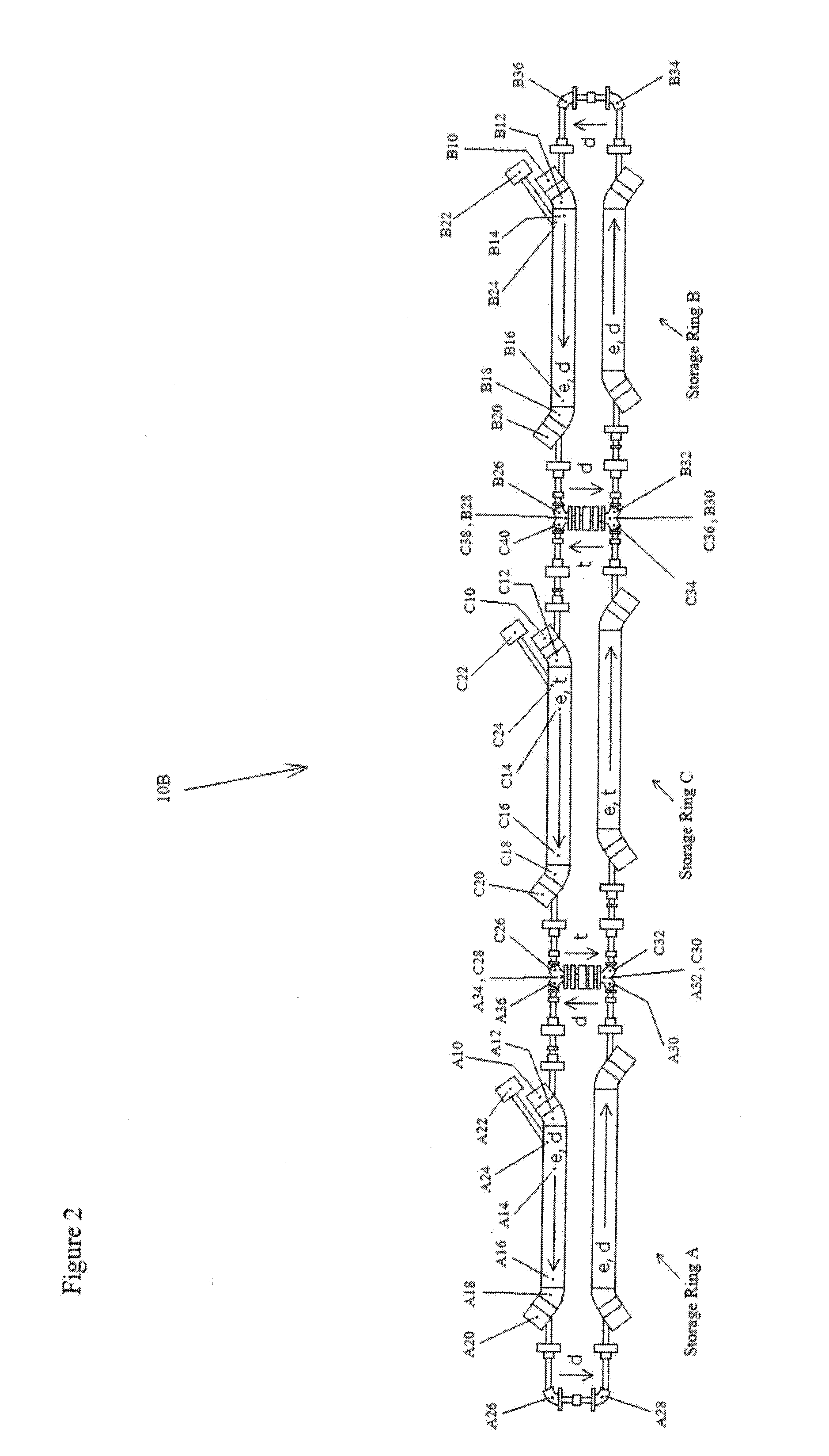
[0027]An electron-cooled intersecting storage ring system 10A employing two intersecting storage rings for achieving controlled nuclear fusion and capable of generating useful levels of electric energy is shown in FIG. 1. An electron-cooled intersecting storage ring system 10B employing three intersecting storage rings for achieving controlled nuclear fusion and capable of generating useful levels of electric energy is shown in FIG. 2. Preferred embodiments can contain four, five, or more intersecting storage rings. In a power plant, the number of intersecting storage rings will be quite large. This description of the preferred embodiments will use deuterium and tritium as the example ions, but, as mentioned in the claims, other ions could be used in the invention as well.

[0028]The electron-cooled intersecting storage ring system 10 utilizes a combination of elements, including an ion source 20 for supplying ions 22, an electron s...


PUM


Abstract

A cellular electron cooled storage ring system and method for achieving particle-fusion based energy, including a vacuum chamber to allow electron beam and ion beam merging and separation, cathodes to generate the electron beams, collectors to collect the electron beams, and magnetic field generation devices to guide the electrons and ions on their desired trajectories as well as contain neutralizing particles. By overlapping the electron and ion beams, thermal energy is transferred from the ion beams to the electron beams, which allows the invention to overcome particle losses due to resonances, scattering and heating of the ion beams. Advantageously, ions are accelerated to an energy that is near optimum for fusion reactions to occur, and uses electron energies that maintain this advantageous situation. Advantageously, the recirculation of ions that do not fuse or scatter at too large of an angle is allowed, giving such ions additional chances to participate in a desired fusion reaction. Advantageously, the invention allows for a continual addition of new ions to be added to the circulating ions already in the system. This combination of advantages results in a significant improvement in the predicted output power to input power ratio over previous particle fusion technologies.

Description

FIELD OF THE INVENTION[0001]The present invention relates to a device intended to induce particle beam collisions for the purpose of creating usable electrical energy, more particularly, to a method and system that achieves extremely high density, low energy ion beams by overlapping the beams with a properly formed electron beam, and furthermore, guides and focuses the ion beams into collision with each other within a very small collision area. Each of the colliding beams is contained in its own storage ring, with electron cooling sections on opposing sides of the ring. Each storage ring also has one or more sections that overlap a section from an adjacent storage ring, and it is in these overlapping sections that the beams are brought into collision and fusion energy is released.BACKGROUND OF THE INVENTION[0002]It has been known for decades that the power generated by the stars, including our own sun, comes from a chain of nuclear reactions that fuse hydrogen into heavier elements....

Claims


Application Information

Patent Timeline
Patent Type & Authority Applications(United States)
IPC IPC(8): G21B1/00
CPCG21B1/00Y02E30/16H05H7/06G21B1/15Y02E30/10
Inventor LARSON, DELBERT J.
Owner LARSON DELBERT J
Learn More