
Adaptive traffic signal phase change system

a traffic signal and phase change technology, applied in the direction of road vehicle traffic control, traffic control of traffic signals, controlling traffic signals, etc., can solve the problems of inability to detect traffic, current systems are not aware of traffic, and data may not be valid at locations other than detectors, so as to reduce maintenance costs and increase traffic flow

Inactive Publication Date: 2008-08-28
SUMNER ROY
View PDF16 Cites 54 Cited by
  • Summary
  • Abstract
  • Description
  • Claims
  • Application Information

AI Technical Summary

Benefits of technology

[0015]It is an object of the present invention to provide a unique method of using the proposed Vehicle Infrastructure Integration (VII) to optimally and dynamically determine how to maximize traffic signal and traffic throughput.
[0018]Furthermore, the benefits of adaptive control can be realized without detectors. Thus, the removal of signal detectors would reduce maintenance costs while increasing traffic flow.

Problems solved by technology

These approaches to adaptive control suffer from a series of problems.
Often current systems are not aware of traffic that is held in a queue and fails to clear on a given green period.
Assumptions made about the traffic speed that may be correct at the location of the traffic detectors but this data may not be valid at locations apart from the detectors.
For example, erroneous data may be generated when tractor trailers are tabulated as passenger cars.
Finally, there is significant cost associated with the installation and maintenance of the detectors.
Loop detectors break in hot regions due to road distortion and in cold regions due to frost damage.
Video detectors are expensive to install and suffer from a range of problems such as occlusion, shadows and lack of effectiveness in the dark.
However, this method does not employ the use of changing traffic signal timing so as to reduce traffic congestion on a real-time basis and requires sophisticated and complex communication coordination between each vehicle and the traffic control system.

Method used


Image

  • Adaptive traffic signal phase change system
  • Adaptive traffic signal phase change system
  • Adaptive traffic signal phase change system

Examples


Embodiment Construction

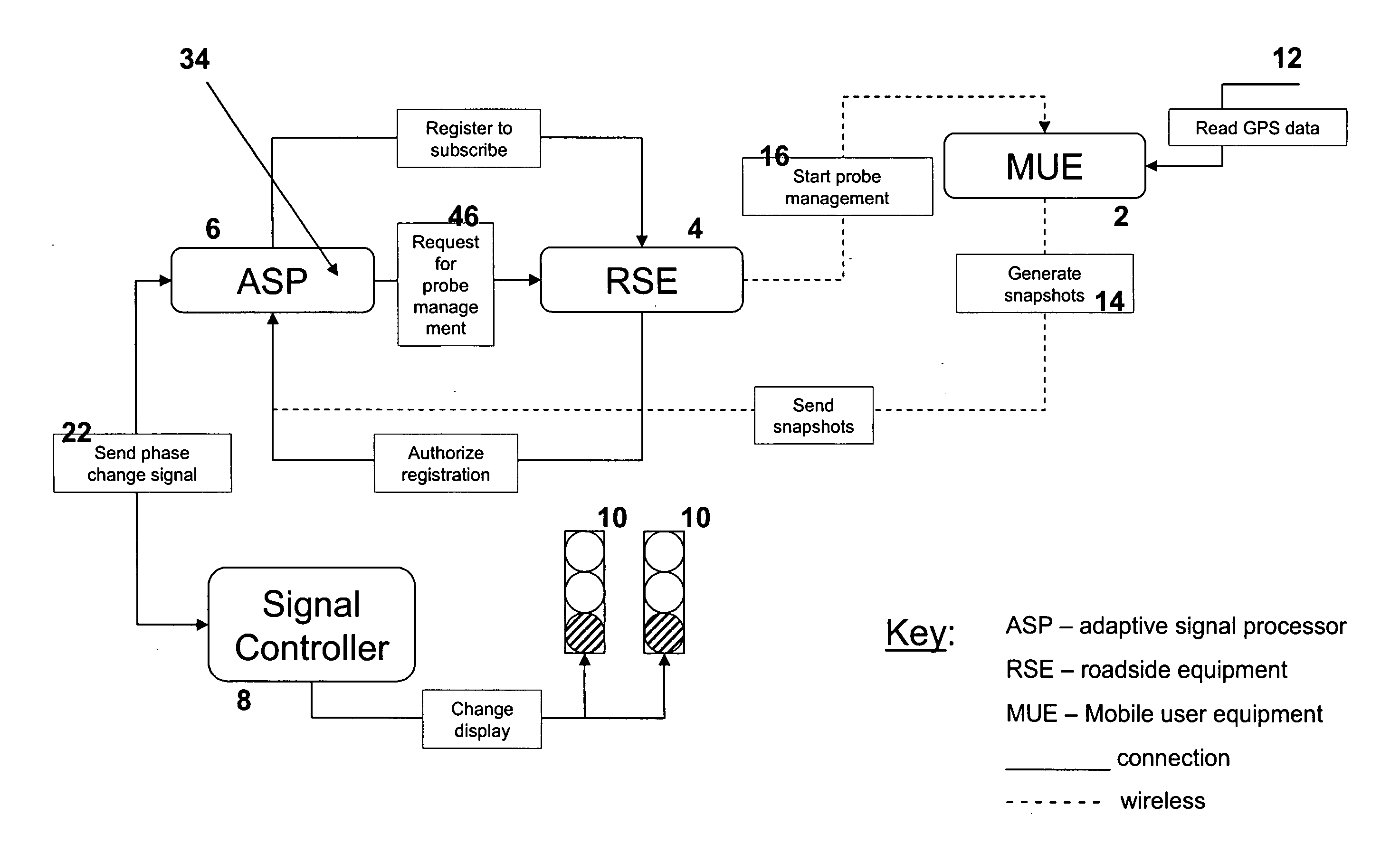
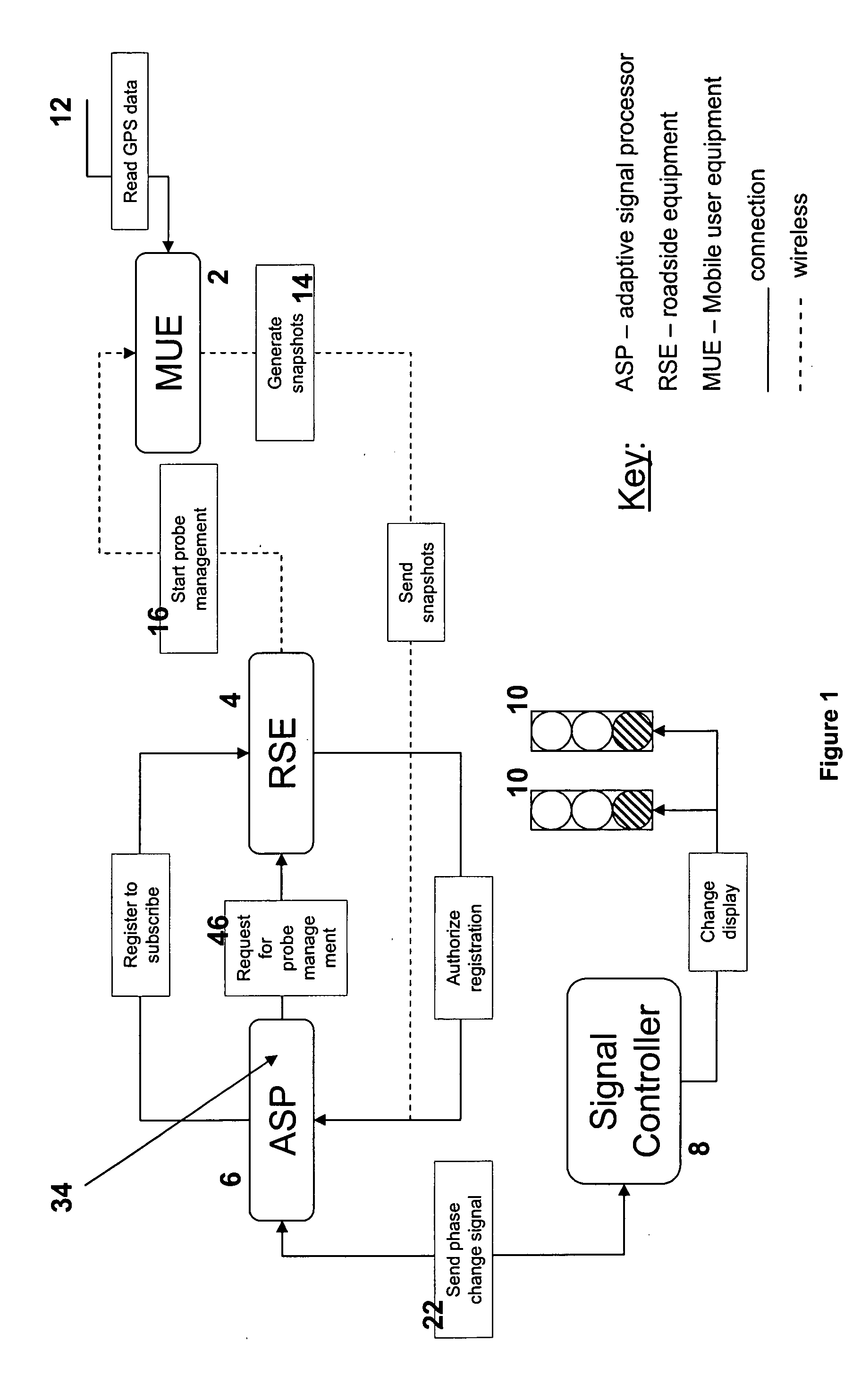
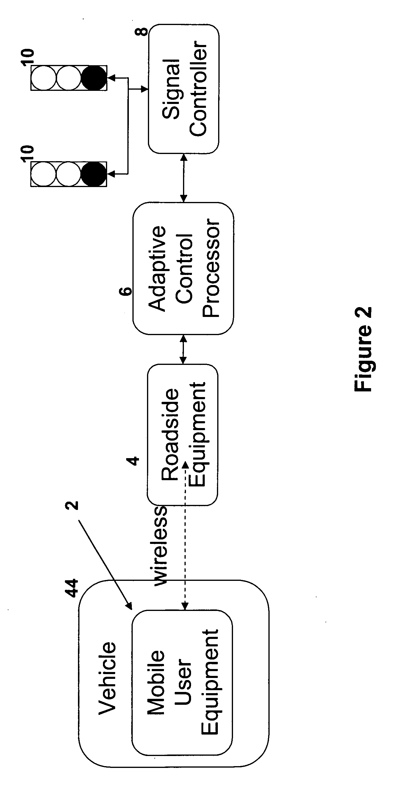
[0026]The adaptive control process of the instant invention consists of series of elements as shown in FIG. 1. They comprise mobile user equipment (MUE) 2 which is intermittently in wireless communication with roadside equipment (RSE) 4. An adaptive control signal processor (ASP) 6 communicates with RSE 4 to inform a signal controller 8 of the optimal time to make phase changes to traffic signals 10, 10′. These elements are structured such that they can be developed as separate software and / or software / hardware modules.

[0027]The flow of events is as follows:

[0028]1. Probe Management to Roadside Equipment

[0029]Referring to FIG. 2, MUE 2 reads real time GPS data 12 through known means to create a series of data snapshots 14 of a vehicle 44 position and movement with respect to a traffic signals 10, 10′. Traditionally, when vehicle 44 is within range of a RSE 4, a single data message containing multiple snapshots 14 is transmitted from vehicle 44 to RSE 4 and no further interaction tak...


PUM


Abstract

This patent provides a process that utilizes the vehicle to infrastructure communication process to gather anonymous vehicle trajectories that describe vehicles approaching a signalized intersection. This information is used to project forward in-time the positions of vehicles to calculate the optimal time to change the traffic signal at a point that will minimize the delay to the traffic.

Description

CROSS REFERENCE TO RELATED APPLICATIONS[0001]This is a continuation-in-part of U.S. Provisional patent application Ser. No. 60 / 903,686 filed on Feb. 27, 2007.BACKGROUND OF THE INVENTION[0002]1. Field of the Invention[0003]The present invention relates to a process which utilizes an infrastructure communication process to gather information on vehicle trajectories approaching a signalized street intersection, and then calculates, from this information, the optimal signal time change to minimize traffic delay and maximize traffic flow.[0004]2. Description of Related Art[0005]Various adaptive control systems to control vehicle traffic flow employing various algorithms have been used to attempt to optimize traffic flow in conjunction with different ways of acquiring data on vehicle movement. U.S. Pat. No. 5,357,436 describes the use of measuring the saturation of traffic at an intersection based on vehicle count to control traffic signals so as to optimize traffic flow, while U.S. Pat. ...

Claims


Application Information

Patent Timeline
IPC IPC(8): G08G1/07
CPCG08G1/08
Inventor SUMNER, ROY
Owner SUMNER ROY
Learn More