
Power device package and semiconductor package mold for fabricating the same

a technology for power devices and molds, which is applied in the direction of semiconductor devices, semiconductor/solid-state device details, electrical equipment, etc., can solve the problems of cracks to be formed in mold members and reduce the reliability and life of power devices

Active Publication Date: 2008-08-28
SEMICON COMPONENTS IND LLC
View PDF84 Cites 49 Cited by
  • Summary
  • Abstract
  • Description
  • Claims
  • Application Information

AI Technical Summary

Benefits of technology

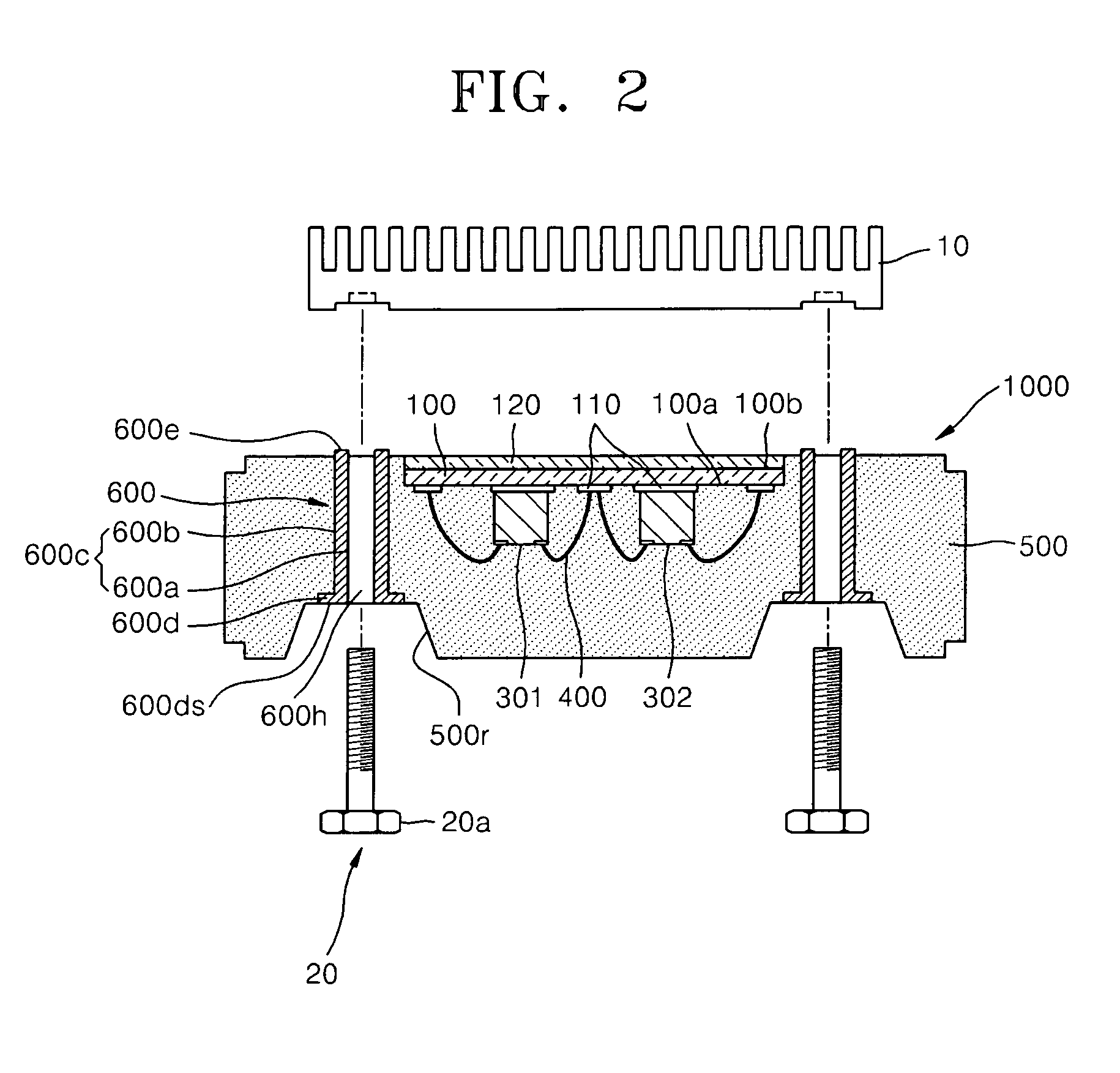
[0010]Embodiments of the present invention provide a power device package coupled to a heat sink using a bolt member, in which a mold member is not damaged during bolt coupling.
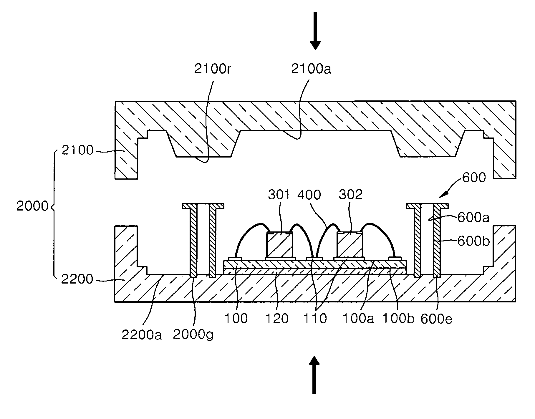
[0011]Embodiments of the present invention also provides a semiconductor package mold for fabricating a power device package in which a mold member is not damaged during bolt coupling during transfer molding.
[0016]In a power device package according to an embodiment of the present invention, a bolt member can be prevented from contacting a surface of the power device package or a compressive stress and a shear stress generated during bolt coupling is reduced by including a bushing member fixed to a mold member. This provides a through hole for a bolt member for coupling a heat sink to a mold member. Accordingly, damage such as cracking of the mold member caused due to the coupling process can be prevented.

Problems solved by technology

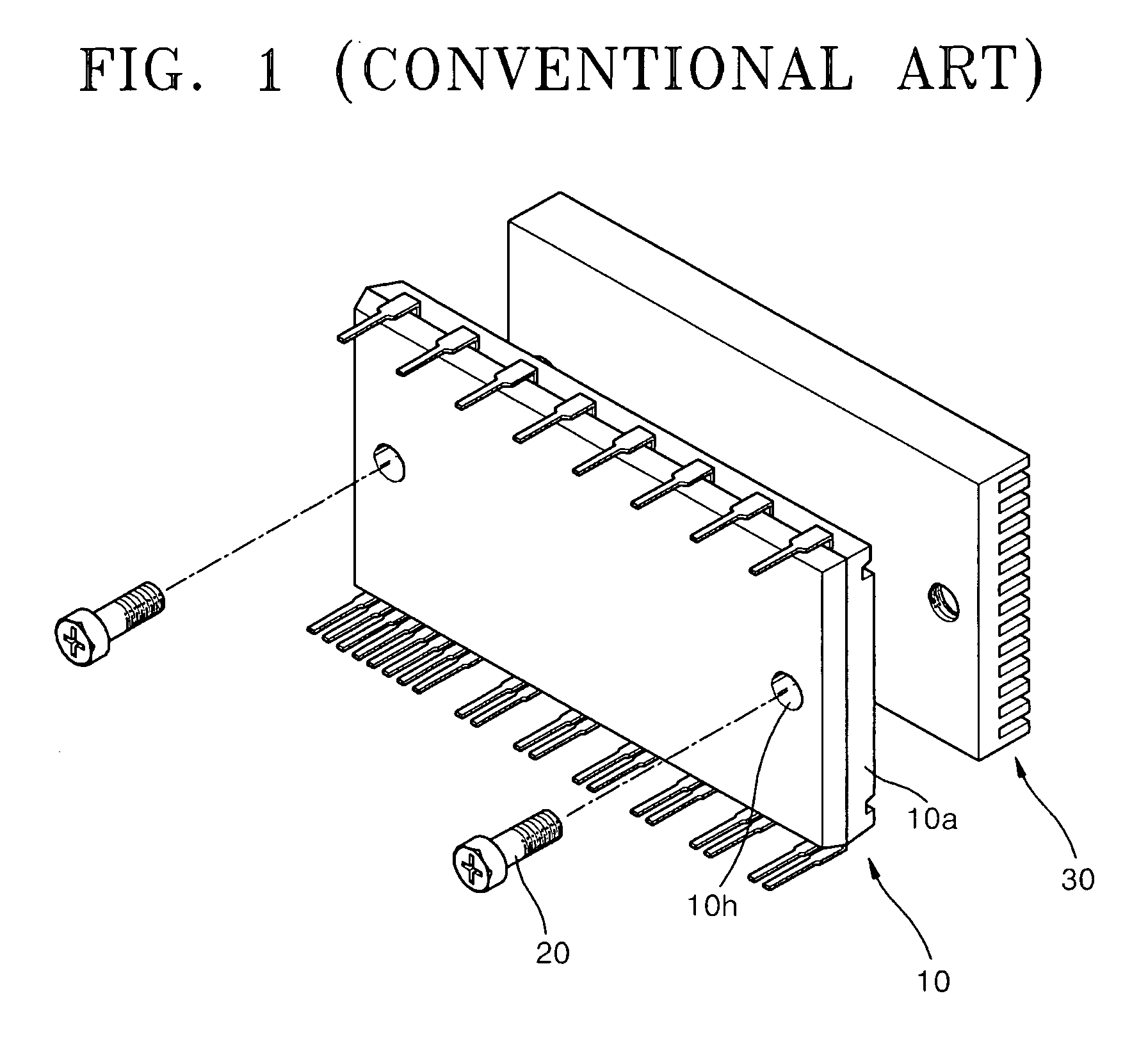
However, when the heat sink 30 is coupled to the power device package 10 using the bolt member 20, compressive stress and shear stress applied to a surface of the power device package 10 may cause cracks to be formed in the mold member 10a.
These cracks formed in the power device package 10 may result in permeation paths of absorbed moisture into the power device package 10 or the insulation break-down, eventually reducing the reliability and life of the power device.

Method used


Image

  • Power device package and semiconductor package mold for fabricating the same
  • Power device package and semiconductor package mold for fabricating the same
  • Power device package and semiconductor package mold for fabricating the same

Examples


Embodiment Construction

[0024]Embodiments of the present invention will now be described more fully with reference to the accompanying drawings, in which exemplary embodiments of the invention are shown.

[0025]Embodiments of the invention may, however, be embodied in many different forms and should not be construed as being limited to the embodiments set forth herein; rather, these embodiments are provided so that this disclosure will be thorough and complete, and will fully convey the concept of the invention to those skilled in the art. It will be understood that when a layer is referred to as being “on” another layer, it can be directly on the other layer, or intervening layers may also be present. In the drawings, the dimensions of layers are exaggerated for clarity of illustration, and like reference numerals in the drawings denote like elements. In the specification, terms “and / or” include one element and all combination of listed elements.

[0026]It will be understood that although the terms first and ...


PUM


Abstract

Provided are a power device package coupled to a heat sink using a bolt and a semiconductor package mold for fabricating the same. The power device package includes: a substrate; at least one power device mounted on the substrate; a mold member sealing the substrate and the power device; and at least one bushing member fixed to the mold member to provide a through hole for a bolt member for coupling a heat sink to the mold member.

Description

CROSS-REFERENCES TO RELATED APPLICATIONS[0001]This application claims the benefit of Korean Patent Application No. 10-2007-0020564, filed on Feb. 28, 2007, in the Korean Intellectual Property Office, the disclosure of which is incorporated herein in its entirety by reference.BACKGROUND OF THE INVENTION[0002]1. Field of the Invention[0003]Embodiments of the present invention relate to a semiconductor package and a semiconductor package mold for fabricating the same, and more particularly, to a power device package coupled to a heat sink using a bolt and a semiconductor package mold for fabricating the same.[0004]2. Description of the Related Art[0005]Power devices, such as silicon-controlled rectifiers (SCR), power transistors, insulated-gate bipolar transistors (IGBT), metal-oxide-semiconductor (MOS) transistors, power rectifiers, power regulators, inverters, converters, and semiconductor devices comprising a combination thereof, are designed to operate in a voltage range of 30-1000...

Claims


Application Information

Patent Timeline
Patent Type & Authority Applications(United States)
IPC IPC(8): H01L23/34
CPCH01L21/565H01L23/3107H01L23/4006H01L2023/405H01L2023/4087H01L2224/45139H01L2924/13055H01L2924/13034H01L2224/48091H01L2224/73265H01L2924/1305H01L2924/13091H01L2924/00014H01L2924/00H01L2924/00011H01L2224/45015H01L2924/207H01L2924/01049H01L23/28
Inventor LEE, KEUN-HYUKLIM, SEUNG-WONPARK, SUNG-MIN
Owner SEMICON COMPONENTS IND LLC
Learn More