
Manual noncontact IC card reader

Inactive Publication Date: 2008-08-28
HITACHI OMRON TERMINAL SOLUTIONS CORP
View PDF5 Cites 12 Cited by
  • Summary
  • Abstract
  • Description
  • Claims
  • Application Information

AI Technical Summary

Benefits of technology

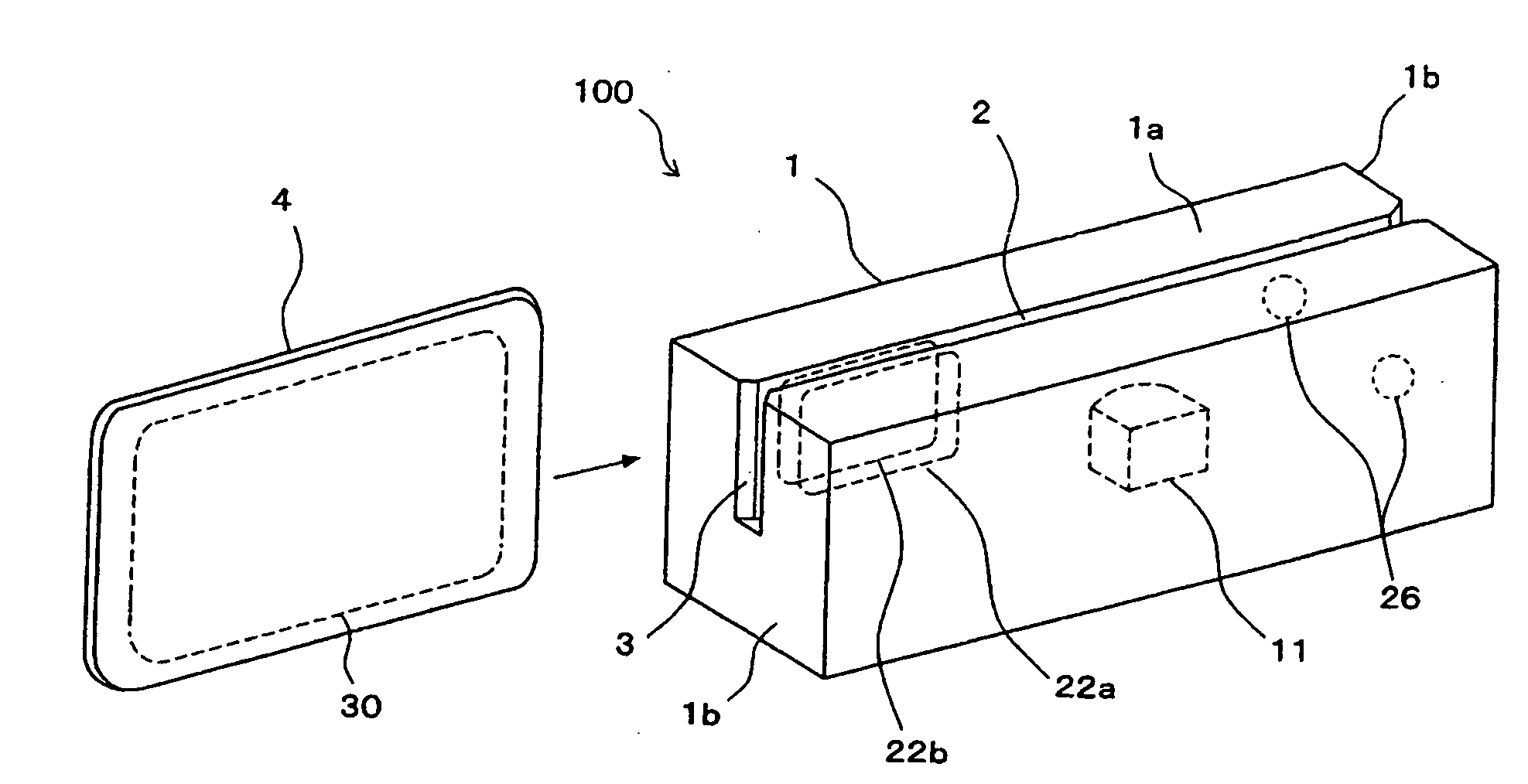
[0015]In the case of a manual noncontact card reader (especially one of swipe type), the transport speed of the card is slower in the initial stage of inserting the noncontact card through the card insertion slot, and thus by locating the loop antennas in proximity to the card insertion slot as described above, communication between the loop antennas on the card reader side and a loop antenna on the noncontact card side may take place with the card moving at slow speed. A state of stable communication between the two is achieved thereby, and the information recorded on the noncontact card may be read accurately, even if the loop antennas on the card reader side are small. Furthermore, by connecting the loop antennas through a magnetic circuit which does not lie exposed within the transport path, of the magnetic fluxes produced in two directions with respect to the noncontact card from the loop antennas, one of them will be diverted through the magnetic circuit without interlinking to the card, and thus the magnetic flux interlinking with the card is constituted by magnetic flux in one direction only, thereby avoiding weakening of the interlinked magnetic flux. Accordingly, high transfer efficiency is achieved and, coupled with the fact that communication takes place with the card moving at slow speed as mentioned above, it is possible for communication to take place in a reliable manner even where small loop antennas are used. Furthermore, since there are no limitations as to the noncontact card transport direction or structure of the transport path, implementation is possible generally in a wide range of manual noncontact card readers.
[0017]As mentioned above, in the initial stage of card insertion the card transport speed is slow and thus a longer communication interval may be assured by initiating communication with the card while in proximity to the card insertion slot. Thus, where the second loop antennas are located to either side of the card insertion slot, generation of magnetic flux and interlinkage thereof with the card may take place to the front of the insertion slot, thereby ensuring a communication period of sufficient duration so that more stable communication may take place. Moreover, because the respective loop antennas are disposed to either side of the card insertion slot and in proximity to the card insertion slot of the transport path, the magnetic field generated by the loop antennas will be quite strong, and high transfer efficiency with the noncontact card may be achieved despite small size of each antenna.
[0020]According to the present invention, since communication with the antennas takes place with the card moving at slow speed during initial insertion of the noncontact card, card information may be read accurately through stable communication, even where the antennas on the card reader side are small. Moreover, as the present invention involves no limitations as to the card transport direction or structure of the transport path, implementation is possible generally in a wide range of manual noncontact card readers, whether of insertion type or swipe type.

Problems solved by technology

However, with manual noncontact card readers, unlike motor-driven types, the card is manipulated by hand, and thus in some instances the card will not be transported at a uniform speed, making it difficult to accurately read the data.
Moreover, with swipe type units, since only part of the card passes through the card transport path, the opposed areas of the antenna on the reader side and the antenna on the card side are of small dimensions, creating the problem of poor transfer efficiency and inconsistent communication between the two.
However, the technology for the insertion type card readers cannot be implemented in swipe type or other card reader that lacks a fixed position where stable communication with the antenna can take place.
In the one swipe type card readers, owing to the special construction employed for the purpose of changing the card transport direction at midpoint, it would not be possible to implement the design in a swipe card reader that has a fixed transport direction.
The limitations imposed by this particular structure pose an obstacle to implementation in swipe card readers generally.
Therefore, it will be difficult to install such a large antenna in the limited space of a compact card reader.

Method used


Image

  • Manual noncontact IC card reader
  • Manual noncontact IC card reader
  • Manual noncontact IC card reader

Examples


Embodiment Construction

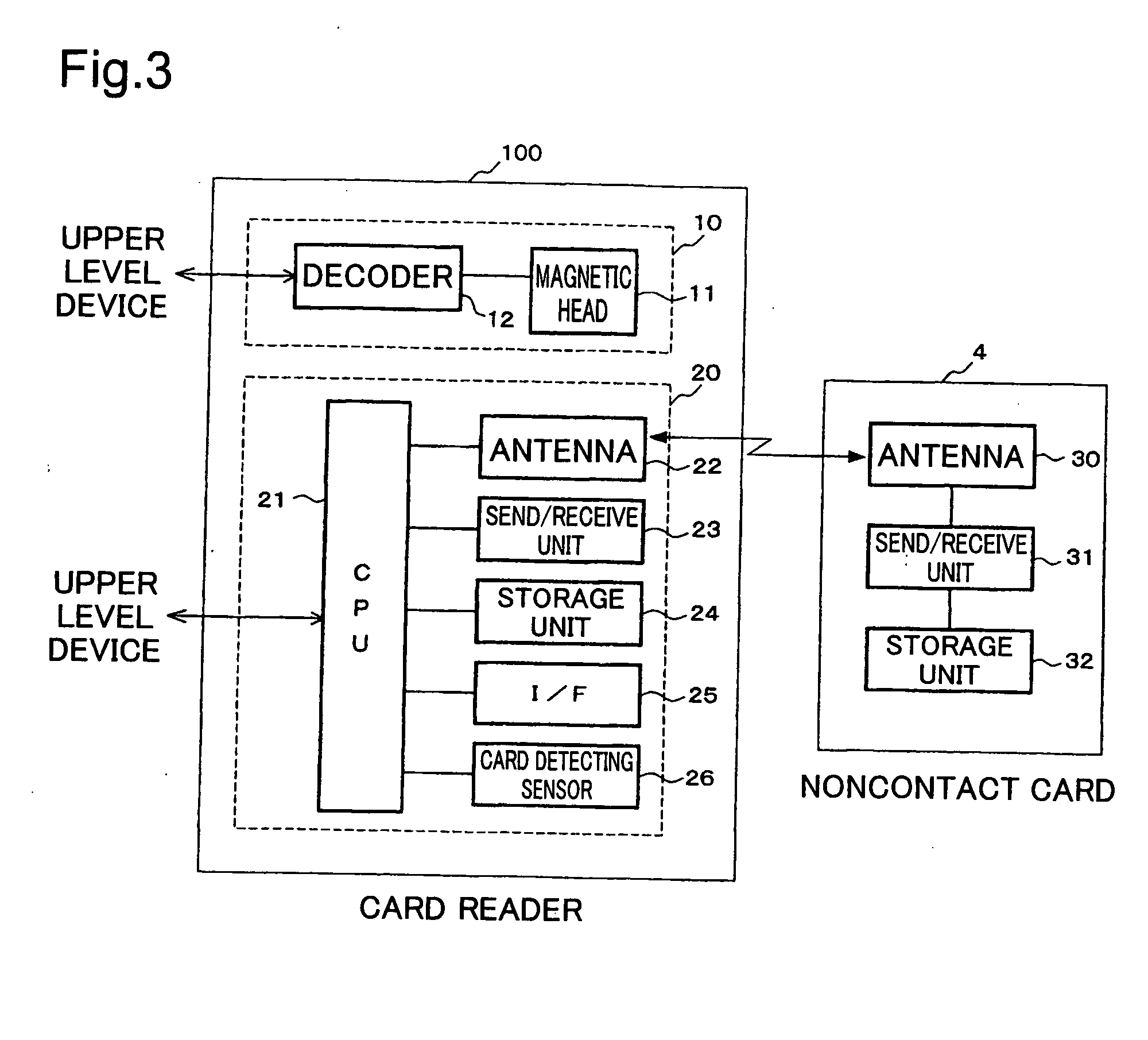
[0036]The preferred embodiments of the present invention will be described in detail below with reference to the accompanying drawings. FIG. 1 is a perspective view showing a manual noncontact card reader (hereinbelow termed simply “card reader”) pertaining to an embodiment of the present invention. 100 denotes a swipe type card reader having a card transport path 2 formed in a main body 1. This transport path 2 opens onto the upper face 1a of the main body 1 as well as onto both end faces 1b; the opening on a first end face 1b of the main body 1 constitutes a card insertion slot 3 for inserting a card 4 in the direction of the arrow. The card 4 is a noncontact card furnished with a loop antenna 30. A pair of loop antennas 22a and 22b for communicating with the loop antenna 30 of the noncontact card 4. The pair of loop antennas 22a and 22b is disposed in opposition across the transport path 2 in proximity to the card insertion slot 3 of the transport path 2. Accordingly, the antenna...


PUM


Abstract

A technology that is applicable generally to manual noncontact card readers regardless of whether they are of insertion or swipe type, and realizes stable communication even with antennas of small size is provided. A pair of loop antennas 22a, 22b is located in opposition to either side of a transport path 2, in proximity to a card insertion slot 3 of the transport path 2. A magnetic circuit 40 which connects the loop antennas 22a, 22b together is located so as to not lie exposed in the transport path 2, so that, of the magnetic fluxes produced in two directions with respect to the noncontact card from the loop antennas 22a, 22b, one of these will be diverted through the magnetic circuit 40 without interlinking to the card.

Description

[0001]The present application claims priority from Japanese application JP2007-046503 filed on Feb. 27, 2007, the content of which is hereby incorporated by reference into this application.BACKGROUND OF THE INVENTION[0002]The present invention relates to a manual noncontact card reader for use in, for example, an entry and exit management system.[0003]Card readers are generally classified motor-driven types and manual types. The motor-driven type card reader draws the card into the inside automatically by a motor-driven transport mechanism so that card information can be read. The manual type card reader manipulates the card by hand so that card information can be read. Manual type card readers are further classified as swipe type card readers which read information as the card is fed in one direction by hand, and insertion type card readers which read information by manually inserting the card into an insertion slot and then withdrawing the card.[0004]While systems such as entry-ex...

Claims


Application Information

Patent Timeline
IPC IPC(8): G06K7/08G06K13/00G06K7/01
CPCG06K7/0008G06K7/10316H01Q7/00H01Q1/2208H01Q1/2225G06K7/10336
Inventor WAKABAYASHI, NAOYUKITADAMASA, AKIHIRO
Owner HITACHI OMRON TERMINAL SOLUTIONS CORP
Learn More