
Distance Measurement Method and Device Using Ultrasonic Waves

a distance measurement and ultrasonic wave technology, applied in the direction of measurement devices, using reradiation, instruments, etc., can solve the problems of inability to amplify the size of signals above noise, lack of practicality, etc., and achieve accurate distance calculation, high precision control, and simple construction

Inactive Publication Date: 2008-08-14
KT CORP
View PDF7 Cites 17 Cited by
  • Summary
  • Abstract
  • Description
  • Claims
  • Application Information

AI Technical Summary

Benefits of technology

The present invention provides a novel method and apparatus for measuring a distance using ultrasonic waves. The method and apparatus of the invention have several technical effects. Firstly, they can effectively control the distance measurement, allowing for stable and accurate distance calculation. Secondly, they can be manufactured relatively inexpensively, making them suitable for various industries. Thirdly, they can measure the distance using a simpler method and apparatus, as compared to conventional methods. The technical effects of the invention include improved precision, cost-effectiveness, and practicality for various applications.

Problems solved by technology

However, this technique has a problem in that it may be mal-operated in response to a large noise.
A time-domain signal is transformed into a frequency-domain signal, which is again transformed into a time-domain signal after being digital-processed, so that a high-performance computer is required, thereby lacking practicality.
Therefore, with this conventional method, the size of signal cannot be amplified above the noise.

Method used


Image

  • Distance Measurement Method and Device Using Ultrasonic Waves
  • Distance Measurement Method and Device Using Ultrasonic Waves
  • Distance Measurement Method and Device Using Ultrasonic Waves

Examples


Embodiment Construction

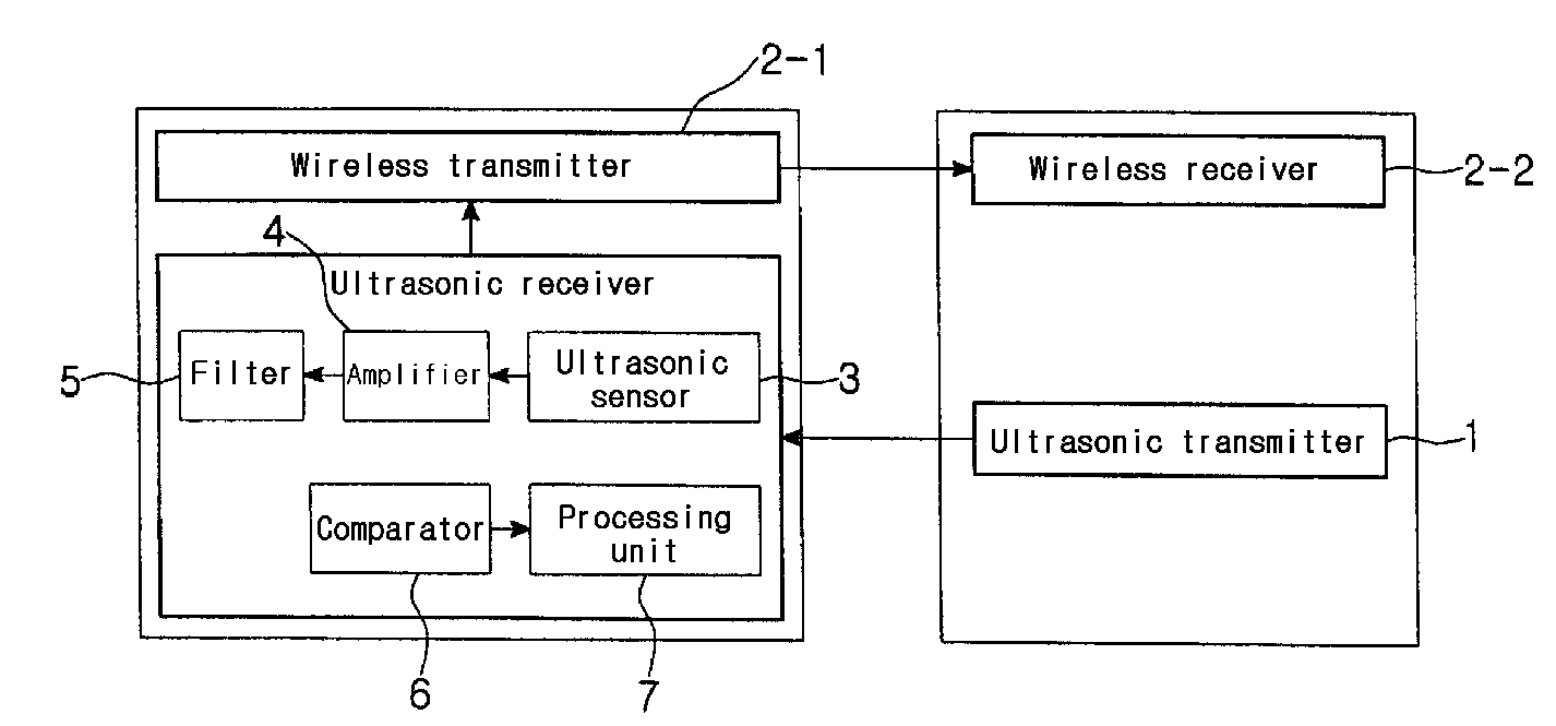
[0027]The preferred embodiments of the present invention will be hereafter described in detail with reference to the accompanying drawings.

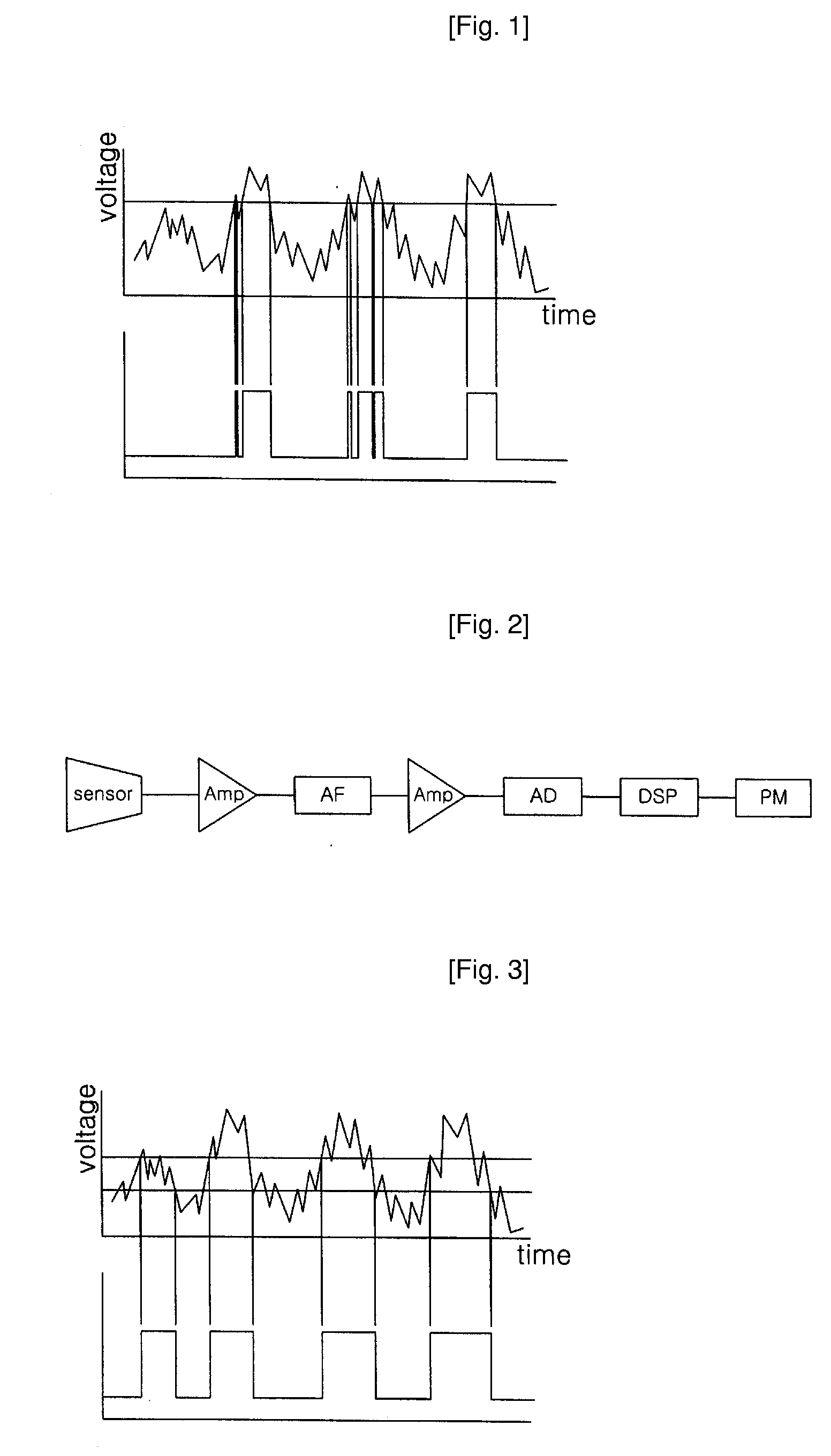
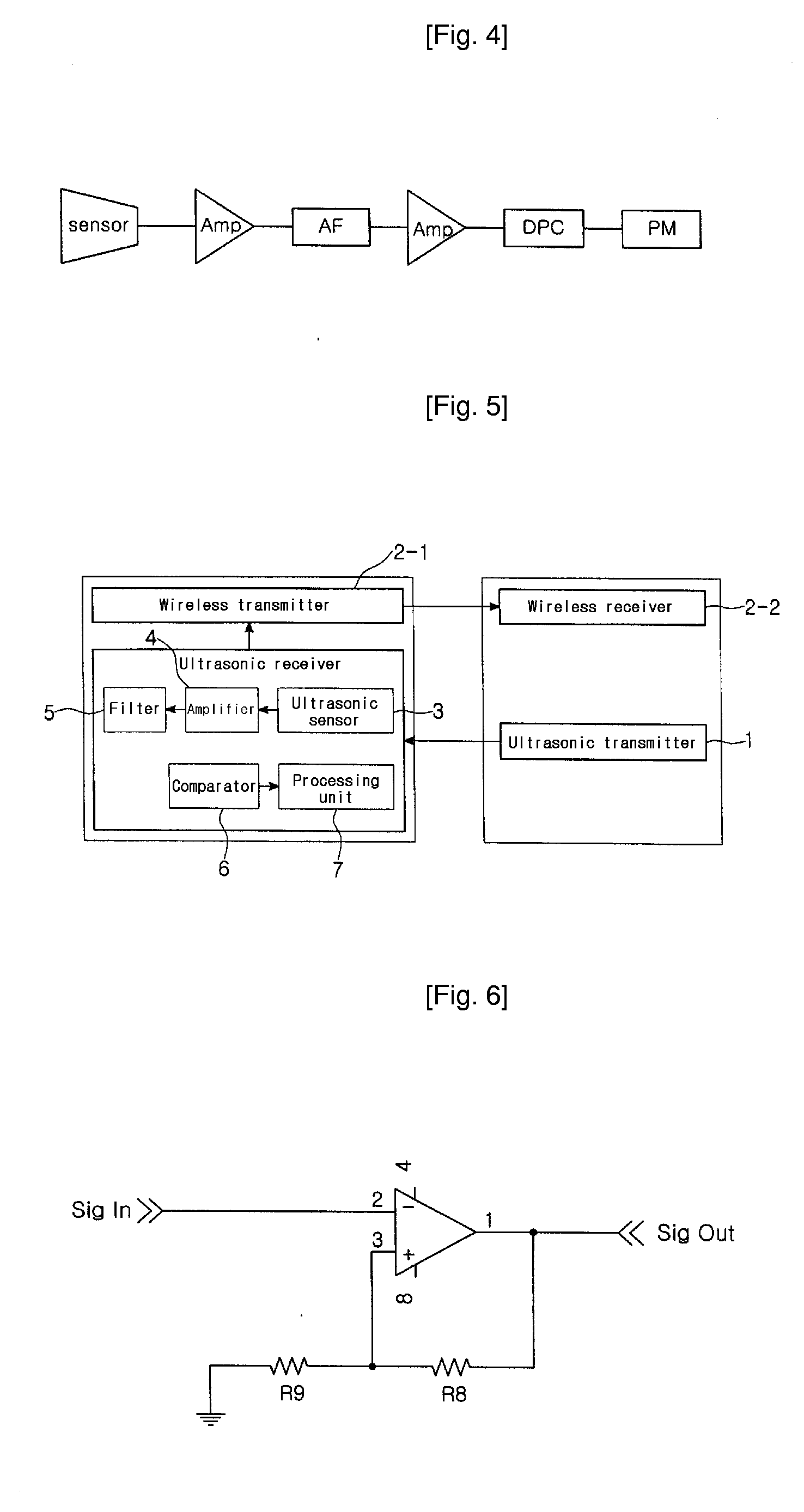
[0028]FIG. 3 is a graph showing a distance measuring method using an ultrasonic wave according to the present invention. FIG. 4 is a block diagram illustrating the processing procedures of a received signal in the method and apparatus according to the invention.

[0029]Referring to FIGS. 1 and 3, the conventional technique and the method according to the invention are compared. First, as shown in FIG. 1, the conventional one determines according to the signal size whether or not a signal is arrived, and thus mal-operation due to noise must be considered. Therefore, the amplification of signal is limited in order for the noise not to become adequately large.

[0030]According to the present invention, however, when the input signal passes upward from below the upper limit, the output signal ascends, and when the input signal passes downward from above ...


PUM


Abstract

The present invention provides a method of and an apparatus for measuring a distance using an ultrasonic wave. The method comprises steps of receiving through an ultrasonic sensor a signal generated from an ultrasonic transmitter according to a signal of ultrasonic transmission time, amplifying the received signal, filtering a high-frequency wave from the amplified signal, outputting only a signal corresponding to a predetermined signal size from the signal in which the high-frequency wave is filtered, and computing a distance value by calculating the period of the output signal. The apparatus comprises an ultrasonic transmitter for transmitting an ultrasonic wave, a device for transmitting a synchronized signal in a wired or wireless mode in order to an ultrasonic transmission signal, an ultrasonic sensor for receiving the ultrasonic signal transmitted from the ultrasonic transmitter, an amplifier for amplifying the received signal to the ultrasonic sensor, a filter for filtering a high-frequency signal from the amplified signal in the amplifier, a comparator for outputting only a signal corresponding to a predetermined signal size from the filtered signal, and an arithmetic unit for computing a distance value by calculating the period of the output signal.

Description

TECHNICAL FIELD[0001]The present invention relates to a method of and an apparatus for measuring a distance using an ultrasonic wave. More specifically, the invention relates to such method and apparatus, in which an ultrasonic signal is transmitted and detected to measure a distance, thereby applying it to various range finder, a lateral positioning device, a factory automation, a mobile robot, a pseudo satellite, or the like.BACKGROUND ART[0002]FIG. 1 is a graph showing a conventional distance measuring method, which decides according the signal size whether a signal is arrived. One example of this type of method is a method of measuring distance using ultrasonic waves, which is disclosed in U.S. Pat. No. 5,197,019 (Delon-Martin, et al.). However, this technique has a problem in that it may be mal-operated in response to a large noise. That is, this technique uses a variable gain in order to maintain constantly the shape of signals. A time-domain signal is transformed into a frequ...

Claims


Application Information

Patent Timeline
Patent Type & Authority Applications(United States)
IPC IPC(8): G01S15/08
CPCG01S11/16G01S7/5273A01K91/053
Inventor AN, HEUI TAYLEE, DONG HWAL
Owner KT CORP
Learn More