Liquid crystal display device and driving method thereof
a technology of liquid crystal display and driving method, which is applied in the direction of static indicating devices, vehicle sub-unit features, instruments, etc., can solve the problems of reducing the size and production cost, deteriorating the picture quality due to unfilled pixel cells, and high power consumption, so as to reduce the fabrication cost and prevent the effect of lowering the picture quality
- Summary
- Abstract
- Description
- Claims
- Application Information
AI Technical Summary
Benefits of technology
Problems solved by technology
Method used
Image
Examples
first embodiment
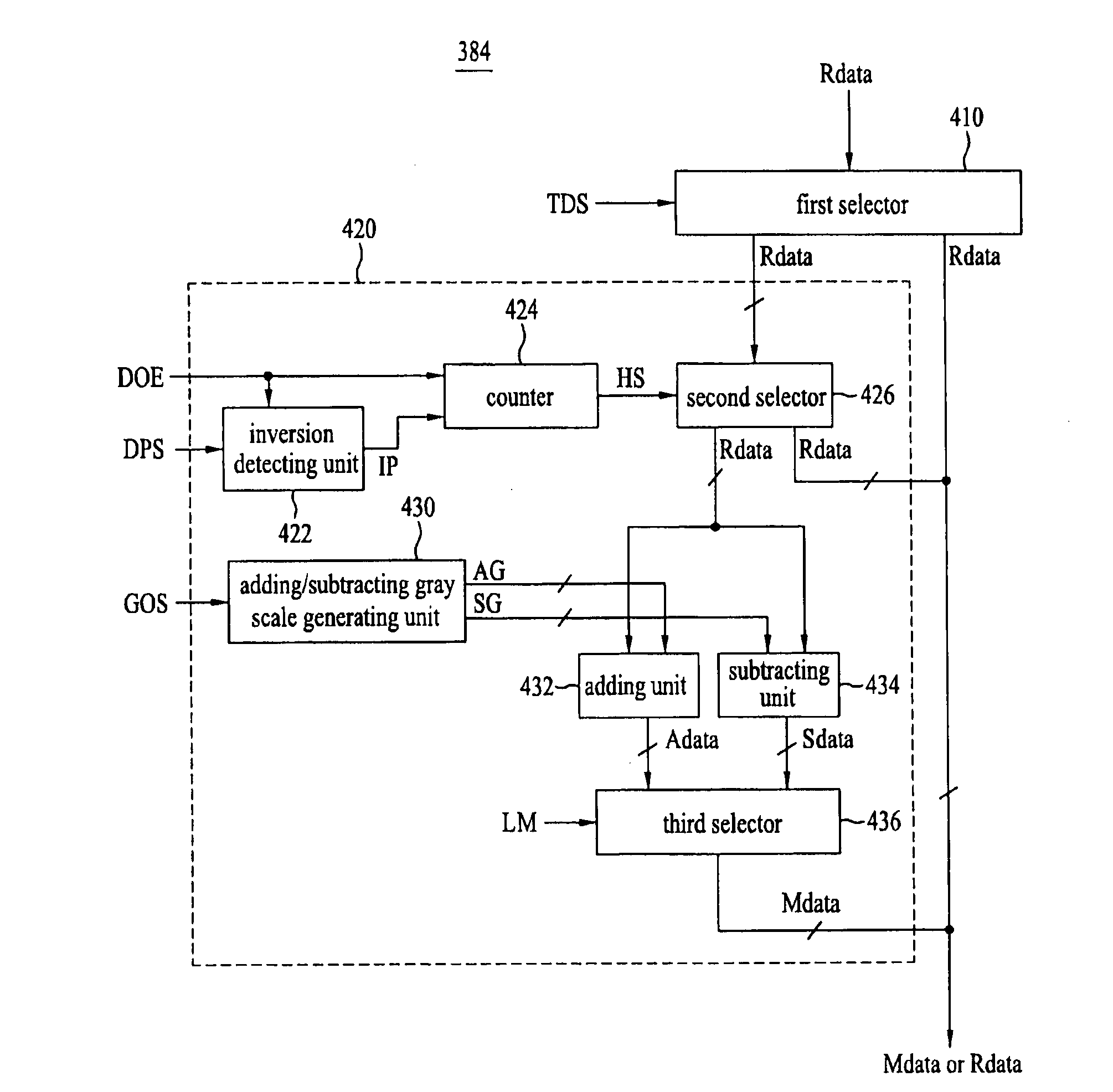
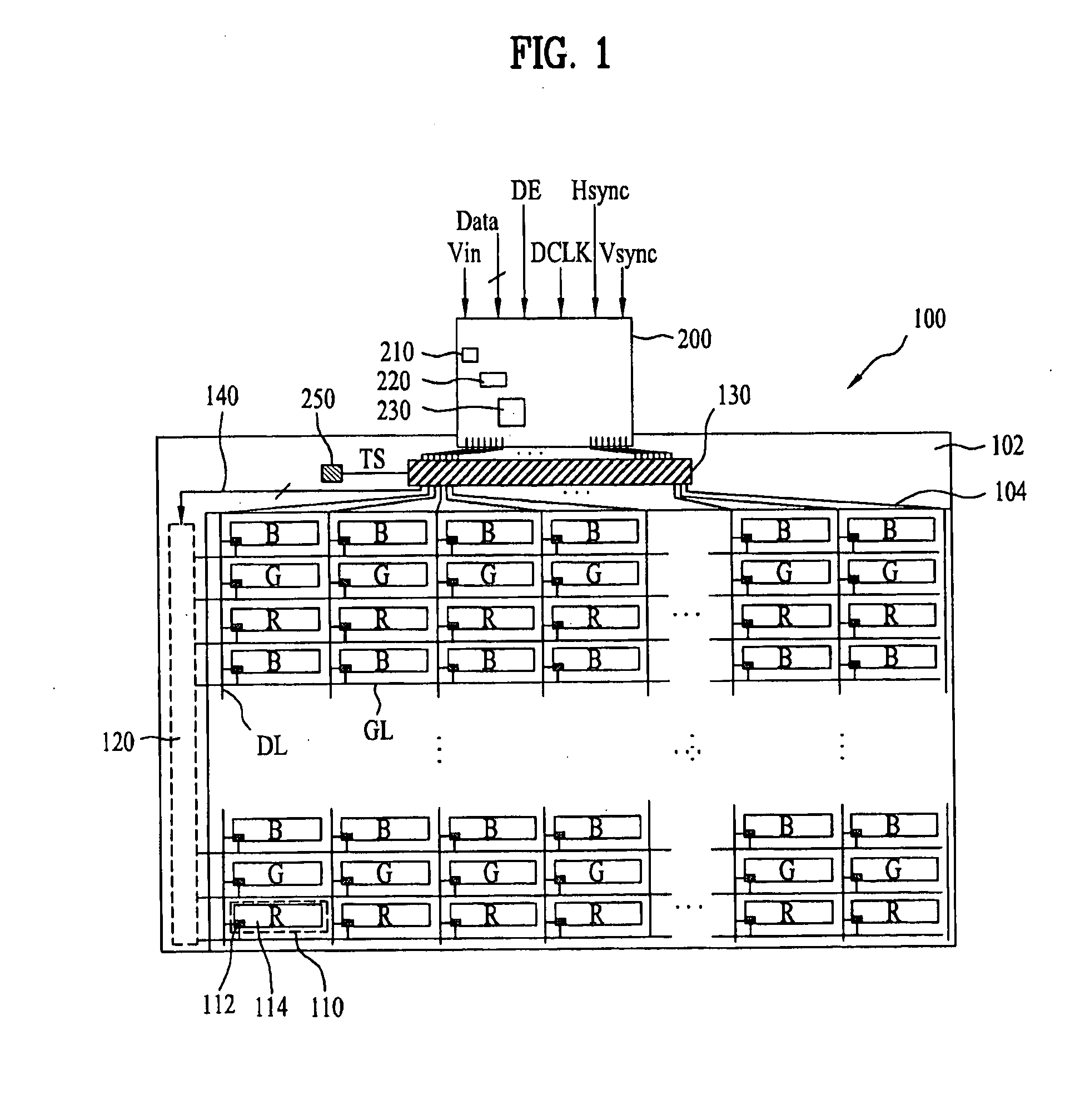
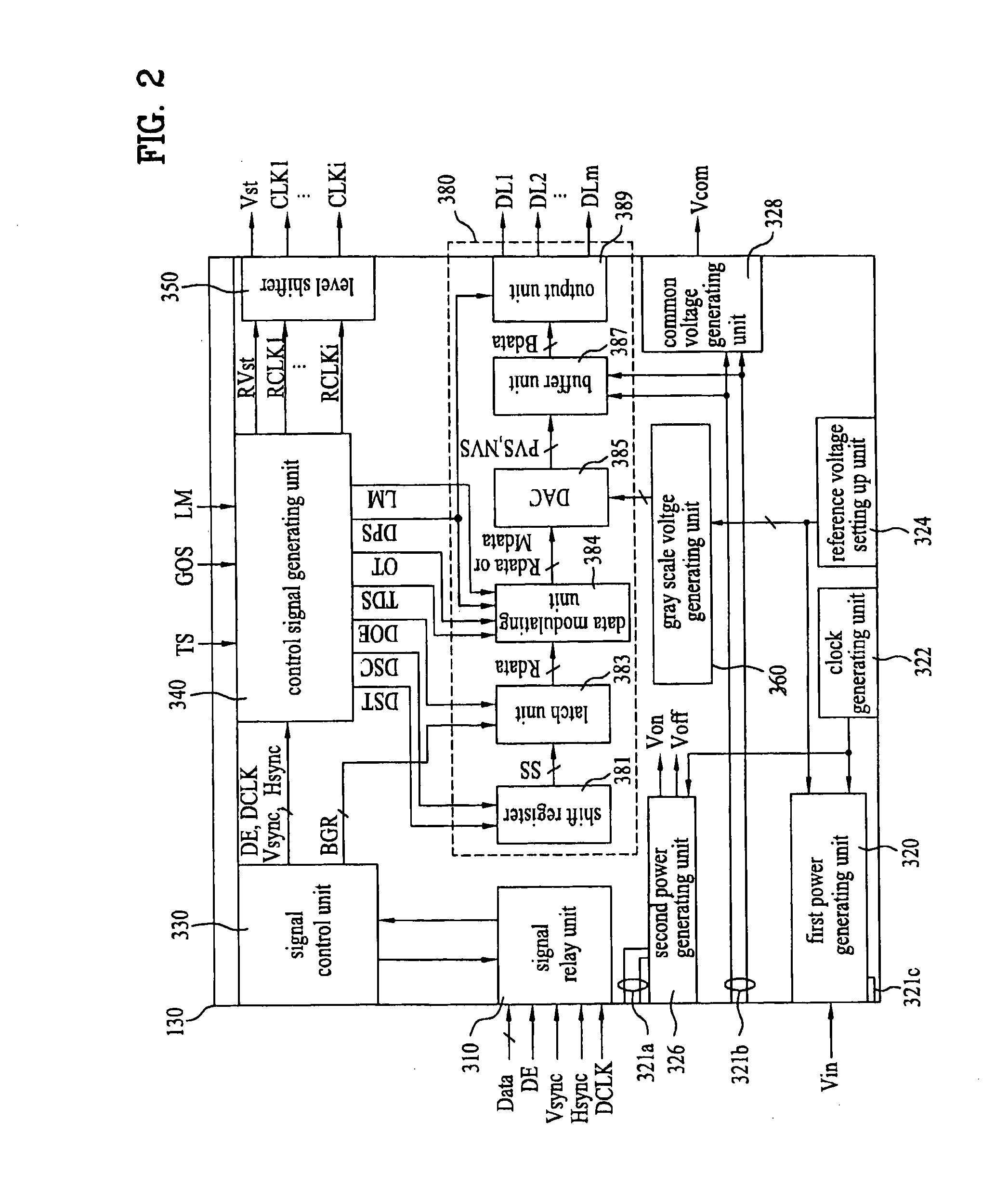
[0079]A method for driving an LCD device according to the present invention will be explained with reference to FIG. 4 in association with FIGS. 1 to 3.
[0080]Supposing that the ambient temperature surrounding the liquid crystal panel 100 is about −10° C., the driving mode of the liquid crystal panel 100 is the normally white driving mode, and that the polarity of the video signal is inverted in the unit of two gate lines. Accordingly, the control signal generating unit 340 generates a temperature detection signal TDS of the second logic state and the driving mode signal LM of the first logic state.
[0081]During the first sub-period of the first horizontal period, and in synchronization with the supply of the gate-on voltage to the first gate line GL1, the modulated positive (+) polarity blue video signal B+ is supplied to the respective data lines DL. Thus, the pixel cells 110 of the first horizontal line display blue video corresponding to the modulated positive polarity blue video ...
second embodiment
[0091]FIG. 6 is a schematic diagram illustrating an LCD device according to the present invention, and polarity patterns of video signals based on a driving method thereof.
[0092]Referring to FIG. 6, except for the polarity pattern of the video signal, the LCD device and its driving method according to the second embodiment of the present invention are identical to those according to the first embodiment of the present invention. Accordingly, a detailed understanding of the identical structural elements may be appreciated from the above description associated with FIGS. 1-4. In the LCD device and driving method of the second embodiment of the present invention, the polarity of video signal supplied to the liquid crystal panel 100 is inverted in the unit of frame as well as in the unit of data line and three gate lines.
[0093]In the LCD device according to the second embodiment of the present invention and the driving method thereof, if the ambient temperature of the liquid crystal pan...
third embodiment
[0095]FIG. 7 is a schematic diagram illustrating an LCD device according to the present invention, and polarity patterns of video signals based on a driving method thereof.
[0096]Referring to FIG. 7, except a polarity pattern of video signal, the LCD device and its driving method according to the third embodiment of the present invention is identical to those according to the first embodiment of the present invention. Accordingly, a detailed understanding of the identical structural elements may be appreciated from the above description associated with FIGS. 1-4. The polarity of video signal supplied to the liquid crystal panel 100 is inverted in the unit of frame as well as in the unit of one data line and four gate lines.
[0097]In the LCD device according to the third embodiment of the present invention and the driving method thereof, if the ambient temperature of the liquid crystal panel 100 is below −5° C., the modulated video signal is supplied to the pixel cells of the (4j-3)th ...
PUM
 Abstract
Description
Claims
Application Information
 - R&D
- Intellectual Property
- Life Sciences
- Materials
- Tech Scout
- Unparalleled Data Quality
- Higher Quality Content
- 60% Fewer Hallucinations
Browse by: Latest US Patents, China's latest patents, Technical Efficacy Thesaurus, Application Domain, Technology Topic, Popular Technical Reports.
© 2025 PatSnap. All rights reserved.Legal|Privacy policy|Modern Slavery Act Transparency Statement|Sitemap|About US| Contact US: help@patsnap.com


