Mounting and suspension system for sliding non-contact displacement and speed measurement

a non-contact displacement and speed measurement technology, applied in the direction of skis, instruments, sport apparatus, etc., can solve the problems of dangerous situation, ski tails are often crossed unintentionally, and the ski tail is a very unwieldy pla

Inactive Publication Date: 2008-08-14
KIRBY COMPANY
View PDF7 Cites 3 Cited by
  • Summary
  • Abstract
  • Description
  • Claims
  • Application Information

AI Technical Summary

Problems solved by technology

First, the tail of a ski is a very unwieldy place to have something that rises above the surface of the ski.
Ski tails are often crossed either unintentionally while skiing or intentionally when using the skating technique, which is very common when starting a run, making a turn at slower speeds, or crossing a flat section of a slope.
Each of the above devices would prevent a skier from crossing the tails of the skis thus provoking a dangerous situation or preventing the skis from being used in one of the required modes of skiing.
In addition to being dangerous and limiting certain ski techniques the tail of a ski as a mounting location has another serious disadvantage as it is subject to very high vibration loads.
Ski Rossignol has measured the vibration on the tail of a ski at up to 1000 g. With this type of force, it would be very hard to keep a tail-mounted device against the snow.
If a spring strong enough to keep the device down were used, it would bend the tail of the ski up off the snow and interfere with the performance of the skis.
However, high edge angles (where most slip occurs), high vibrations (unavoidable on the tail of a ski), and the ski bent into an arc by carving the ski on its edge, would all prevent this device from accurately measuring slippage when mounted behind the tail of the ski.
Additionally, locating the measurement device behind the tail of the ski distorts the measurement of slippage, as ski tails slide much more than the center or tip of the ski.
Mounting a speed detection system inside a ski has a number of serious disadvantages, notably, the ski structure must be modified, which requires the skis to be built at the factory in such a way that they are enabled for the device.
Lastly, a device built into the ski, could not be used with existing skis, substantially reducing the size of the market.

Method used


Image

  • Mounting and suspension system for sliding non-contact displacement and speed measurement
  • Mounting and suspension system for sliding non-contact displacement and speed measurement
  • Mounting and suspension system for sliding non-contact displacement and speed measurement

Examples


embodiment

PREFERRED EMBODIMENT

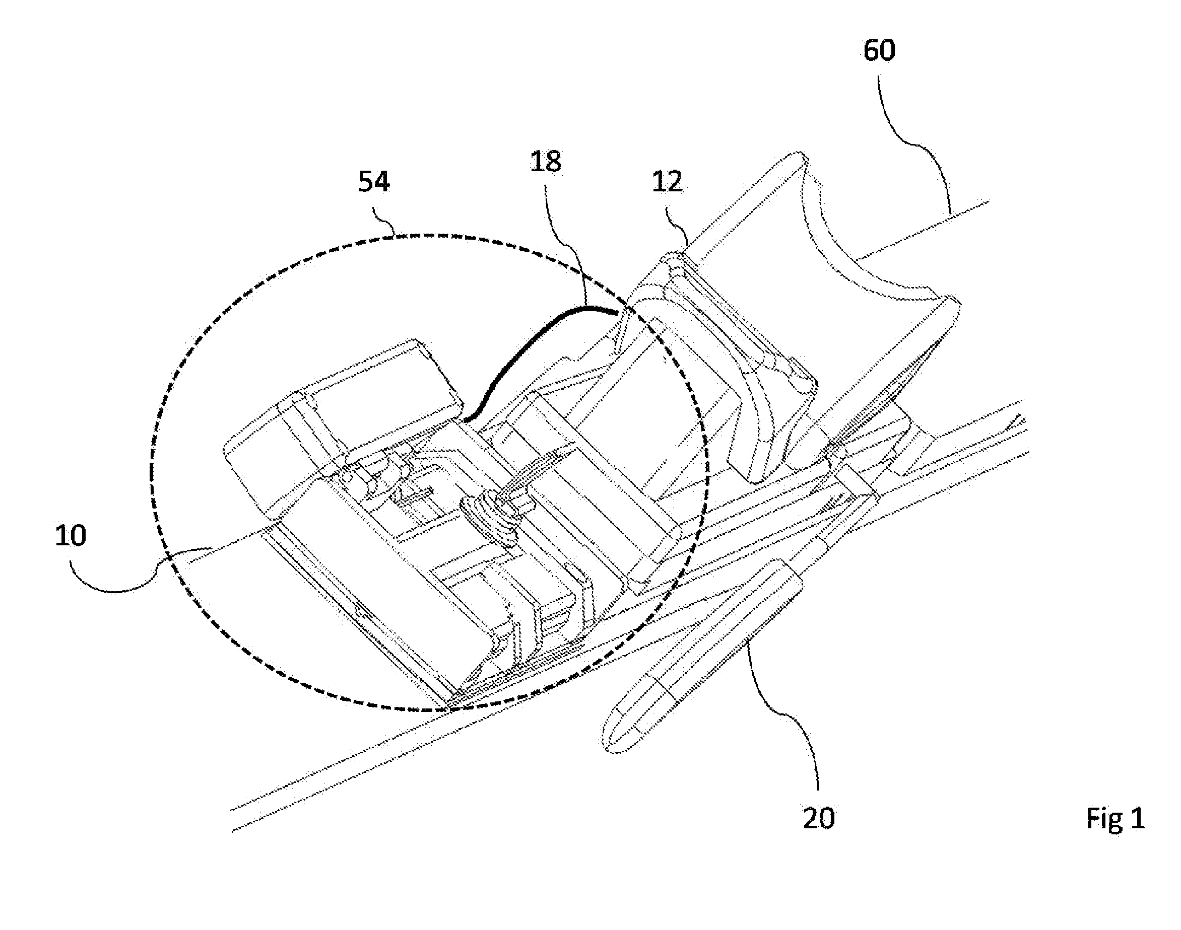
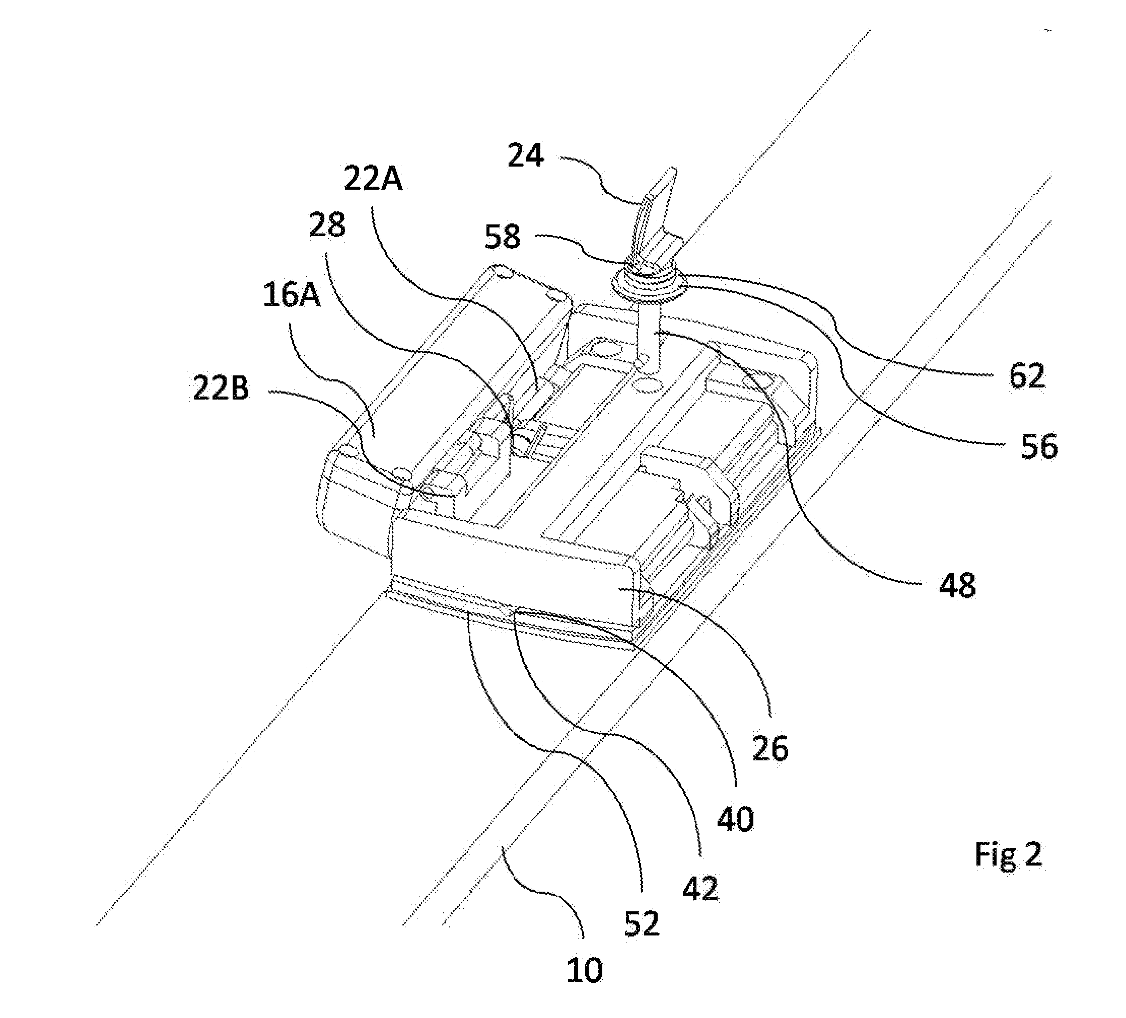
[0065]A preferred embodiment of the mounting and suspension system of the present invention is illustrated in FIGS. 1 through 4. FIG. 1 shows the relative position of the key components of the system. A removable suspension and measurement assembly (54) is attached to a fixed mounting plate assembly (52) shown in FIG. 3. The fixed mounting plate assembly (52) of FIG. 2 is in-turn attached to a ski (10) of FIG. 3 also having a binding (12), a ski brake (20), and a binding plate (60). The preferred attachment location is behind the binding (12) although one skilled in the art could easily conceive of alternative locations including in front of the binding or incorporated in the binding (12) or binding plate (60). In the preferred embodiment, a retraction cable (18) connects the ski brake (20) to a linkage arm (22A) of FIG. 2.

[0066]In FIG. 3, a base plate (30) is attached to the ski (10) by means of an adhesive (38). In the preferred embodiment, the base plate (30) ...


PUM


Abstract

A mounting and suspension system for mounting non-contact sliding measurement devices to the side of objects that slide on snow or ice like skis, snowboards, sleds, luges, and ice skates. A base component permanently attached to the sliding object allows a quick disconnect of the rest of the device. A linkage component permits the retraction of the measurement device relative to the sliding object in such a way that the measurement device remains aligned with the surface being measured while minimizing lateral displacement and fully retracted vertical height such that accurate measurement is obtained at any angle of sliding object relative to the surface of snow or ice. A bias device keeps the measurement device in firm contact with the surface without interfering with the use of the sliding object. A safety device prevents injury to user and damage to measurement device in case of impact with an external obstacle or fall.

Description

CROSS-REFERENCE TO RELATED APPLICATIONS[0001]This application claims the benefit of provisional patent application Ser. No. 60 / 901,107, filed Feb. 14, 2007.FEDERALLY SPONSORED RESEARCH[0002]Not applicable.SEQUENCE LISTING OR PROGRAM[0003]Not applicable.BACKGROUND OF THE INVENTION[0004]1. Field of Invention[0005]This invention relates to devices which measure the displacement of an object sliding across a surface of snow or ice such as a ski, snowboard, sled, luge or ice skate.[0006]2. Prior Art[0007]Numerous methods have been proposed to measure the speed of a ski. Originally these methods used some form of mechanical contact measurement such as a wheel or roller which was attached to the tail of a ski via a spring loaded arm. U.S. Pat. No. 4,136,451 is such a device which consists of a wheel which rolls on the snow surface. The wheel is attached to a spring loaded arm which pivots about an axis which is perpendicular to the axis of the ski but in the plane of the ski. This allows t...

Claims


Application Information

Patent Timeline
Patent Type & Authority Applications(United States)
IPC IPC(8): G01P1/02A63C9/08A63C11/00
CPCA63C5/06A63C2203/18A63C11/00
Inventor KIRBY, RICHARD A.
Owner KIRBY COMPANY
Why Eureka
Try Eureka