Eureka AIR delivers breakthrough ideas for toughest innovation challenges, trusted by R&D personnel around the world.

Machine Tool Comprising a Rotary Transmission Leadthrough Between the Driven Gear and the Spindle

a technology of drive gear and drive shaft, which is applied in the direction of gearing details, attachment milling devices, manufacturing tools, etc., can solve the problems of negative influence and influence of out-of-balance value, and achieve the effect of reducing out-of-balance, ensuring accuracy, and ensuring accuracy

Inactive Publication Date: 2008-08-07
ZF FRIEDRICHSHAFEN AG
View PDF17 Cites 4 Cited by
  • Summary
  • Abstract
  • Description
  • Claims
  • Application Information

AI Technical Summary

Benefits of technology

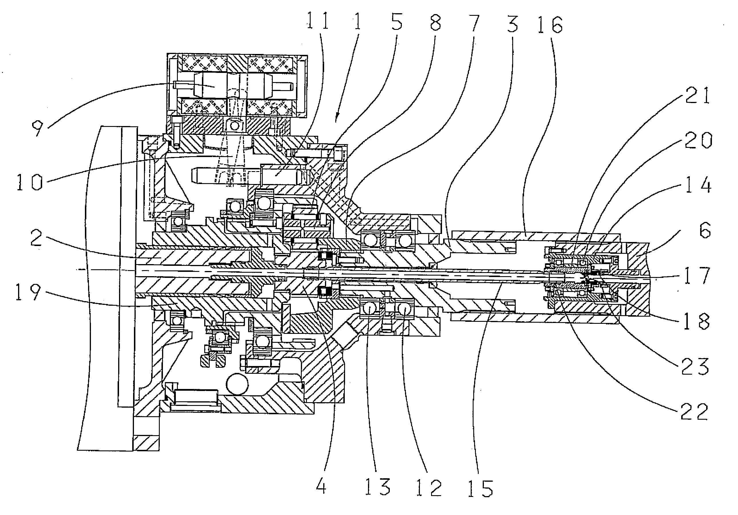
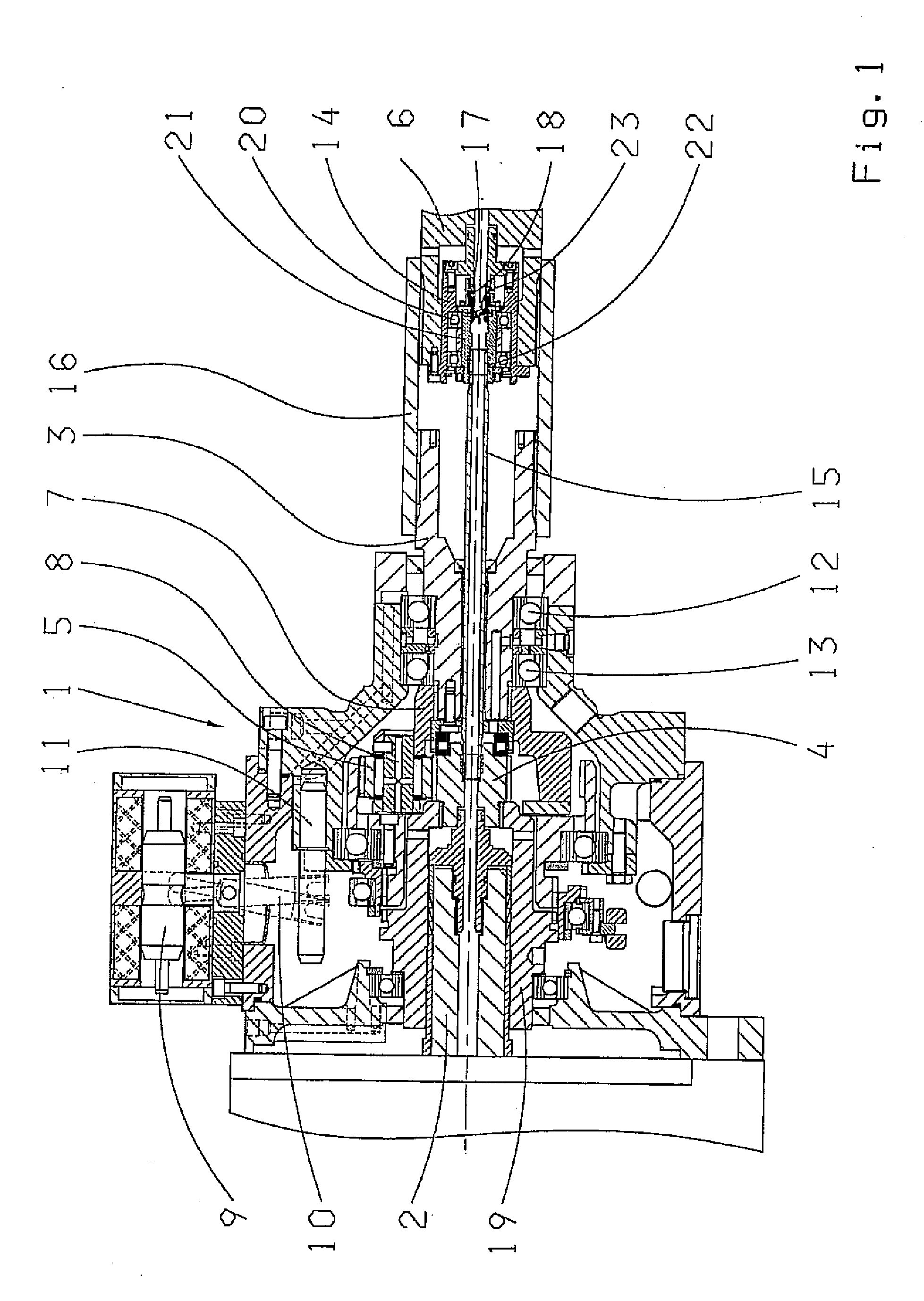
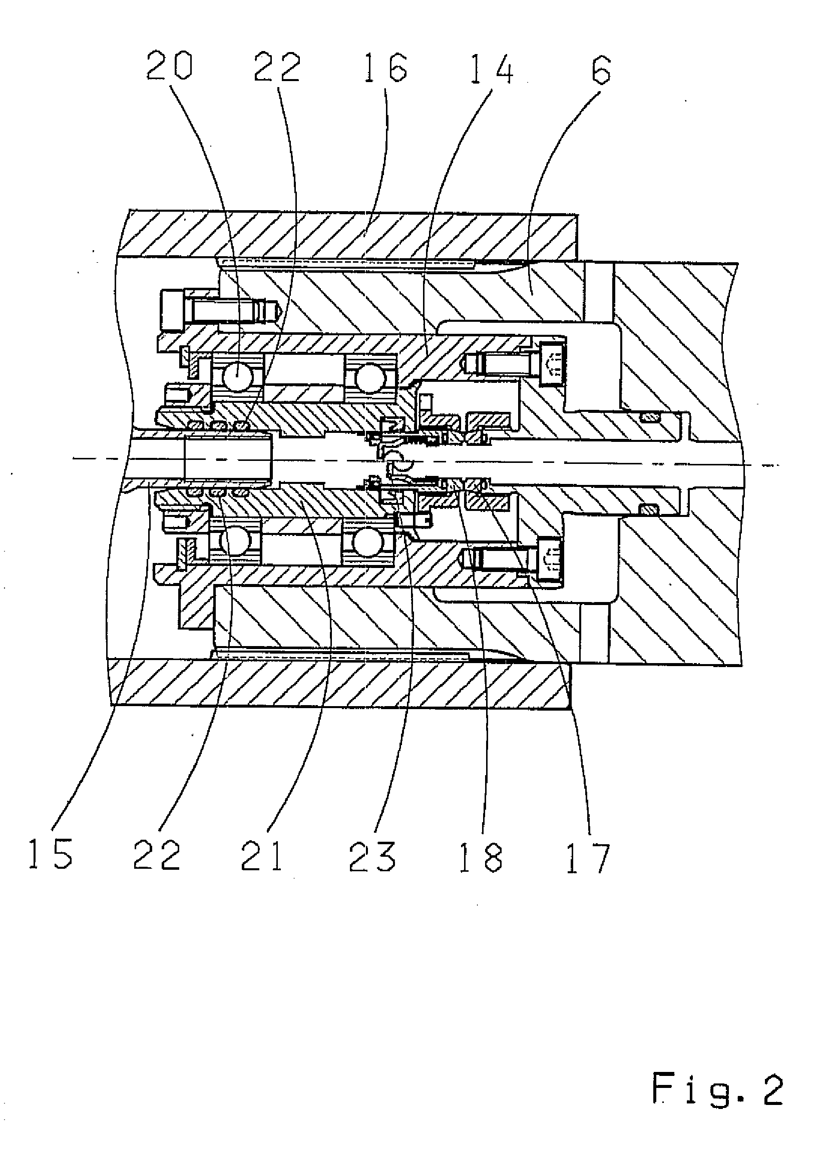
[0014]The inventive arrangement of the rotary passage in the spindle has the advantage that the true running accuracy of the spindle is considerably more precise than that of the output shaft. This produces a lower out-of-balance by the mass of the rotary passage, which is a considerable advantage, particularly at high rotational speeds.
[0016]Due to the inventive design, the sealing point is disposed outside of the gear mechanism, which results in the further advantage that leaks can be permitted and fed directly into a tank.

Problems solved by technology

In this design, the influence of the out-of-balance value, which is caused by the imprecise output shaft bearings compared to the spindle bearings, is negatively influenced due to the integration of the rotary passage in the output shaft.

Method used


Image

  • Machine Tool Comprising a Rotary Transmission Leadthrough Between the Driven Gear and the Spindle
  • Machine Tool Comprising a Rotary Transmission Leadthrough Between the Driven Gear and the Spindle
  • Machine Tool Comprising a Rotary Transmission Leadthrough Between the Driven Gear and the Spindle

Examples


Embodiment Construction

[0020]FIG. 1 shows a machine tool gear mechanism 1, comprising an input shaft 2, an output shaft 3 and a two-stage planetary gearset disposed in the power flow direction between the input shaft and the output shaft, the planetary gearset comprising a sun gear 4 connected to the input shaft 2, a ring gear 5 supported in the ring gear bearing and a planet carrier 7 with planets 8, the carrier forming the output of the planetary gearset.

[0021]The shifting unit of the gear mechanism 1 comprises a solenoid 9, which acts on a shifting fork 10 via a selector shaft 11. In the illustrated example, the output shaft 3 is supported by way of bearings 12, 13 and connected to a spindle 6 via a rigid bushing 16, which engages, via internal gears, the corresponding external gears of the output shaft 3 and the spindle 6. Alternatively to the rigid bushing 16, the connection between the output shaft 3 and spindle 6 can be established via a positive or non-positive clutch.

[0022]With reference to FIGS....


PUM

PropertyMeasurementUnit
torqueaaaaaaaaaa
rotational speedaaaaaaaaaa
pressureaaaaaaaaaa

Abstract

A machine tool gear mechanism (1) such as a spindle gear mechanism, transmits torque from an output shaft (3) of the gear mechanism directly to a spindle (6). The mechanism includes a rotary passage (14) as a device for delivering coolants, emulsions, oils or air between the output shaft (3) or the motor and the spindle (6). The rotary passage (14) is integrated in the spindle (6).

Description

[0001]This application is a national stage completion of PCT / EP2006 / 004595 filed May 16, 2006, which claims priority from German Application Serial No. 10 2005 022 713.9 filed May 18, 2005.FIELD OF THE INVENTION[0002]The present invention relates to a machine tool gear mechanism, particularly a spindle gear mechanism.BACKGROUND OF THE INVENTION[0003]From the state of the art, such machine tool gear mechanisms are known. They typically comprise a two-stage planetary gear system and a corresponding shifting device, such as that described in WO 00 / 63569, so that rotational speed differentials in the gear ratio are produced between the input or the motor shaft and the output. The torque is transmitted from the output shaft of the gear mechanism directly to the spindle, wherein the spindle is preferably disposed co-axially to the output shaft. In such gear mechanisms, the output shaft is directly connected to the spindle; the rotationally fixed connection between the spindle and output s...

Claims


Application Information

Patent Timeline
Patent Type & Authority Applications(United States)
IPC IPC(8): F16H57/04F16J15/50
CPCF16H57/0426F16H57/043Y10T74/19991Y10T409/309352Y10T409/303976F16L27/0828B23Q5/04B23Q5/043B23Q5/54
Inventor ECKERT, HARALD
Owner ZF FRIEDRICHSHAFEN AG
Why Eureka
Eureka Blog
Learn More