Eureka AIR delivers breakthrough ideas for toughest innovation challenges, trusted by R&D personnel around the world.

Motor and method for manufacturing the motor

Active Publication Date: 2006-11-02
MAKITA CORP
View PDF4 Cites 31 Cited by
  • Summary
  • Abstract
  • Description
  • Claims
  • Application Information

AI Technical Summary

Benefits of technology

[0008] It is an object of the invention to provide an improved technique for winding a wire to form an armature winding between a commutator and an armature in a balanced manner.
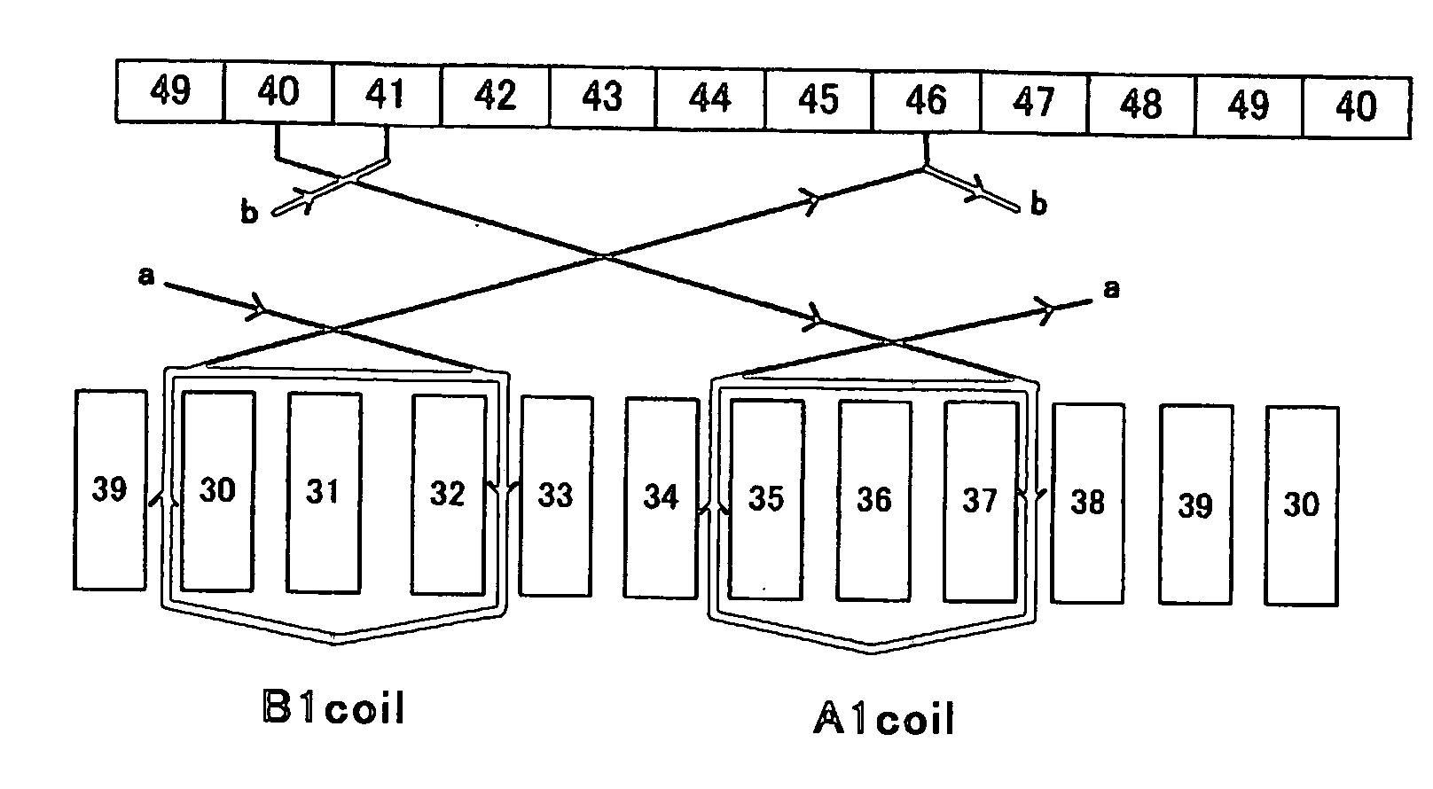
[0017] Specifically, in the motor according to the invention, two kinds of unit windings are provided in which groups of coils in a unit winding of one kind are connected from a starting-point segment to an endpoint segment in a different order from those in a unit winding of the other kind. Therefore, the number of times that the wires are sequentially connected from a segment shifted by one segment to a slot shifted by one slot can be reduced. Thus, problem in the prior art that the wires connected between the commutator and the armature tend to regularly overlap each other to create an imbalance in the wire volume can be alleviated. As a result, the wire for forming the armature winding can be wound between the commutator and the armature in a balanced manner.
[0018] Further, according to the representative motor, the prior art problem can be avoided that the rotor, the armature, the commutator and the armature winding results imbalance in weight causing a deviation of rotating center the rotor from the output shaft, can be avoided. Therefore, in the process of manufacturing the motor, it is not necessary to take time for adjustment of the balance, for example by reducing the weight by partially cutting away the commutator or the armature.
[0021] According to the representative motor, a difference is made between the first unit winding and the second unit winding in the order in which the segments for forming the equalizing wire are connected. Thus, in the armature winding formed by a plurality of unit windings, the problem that the segments shifted by one segment in the circumferential direction around the axis of the commutator are uniformly configured as a starting-point segment can be avoided. As a result, the imbalance of the wire volume between the commutator and the armature winding is prevented.
[0023] Specifically, in the motor manufacturing method of this invention, a difference is made between the first unit winding and the second unit winding in the order in which groups of coils are connected from the starting-point segment to the endpoint segment. the wires connected between the commutator and the armature can be prevented from regularly overlapping each other to cause imbalance in the wire volume.

Problems solved by technology

However, the resistance loss caused by friction between a commutator and the brushes during rotation of an armature may increase with increase in the number of brushes.
As a result, the wires connected between the commutator and the armature tend to regularly overlap each other, so that imbalance in the wire volume is created.
As a result, the rotor, which is formed by the output shaft, the armature, the commutator and the armature winding, has an imbalance in weight and thus the center of rotation of the rotor tends to be displaced from the output shaft.

Method used


Image

  • Motor and method for manufacturing the motor
  • Motor and method for manufacturing the motor
  • Motor and method for manufacturing the motor

Examples


Embodiment Construction

[0045] Each of the additional features and method steps disclosed above and below may be utilized separately or in conjunction with other features and method steps to provide improved motors and method for using such motors and devices utilized therein. Representative examples of the present invention, which examples utilized many of these additional features and method steps in conjunction, will now be described in detail with reference to the drawings. This detailed description is merely intended to teach a person skilled in the art further details for practicing preferred aspects of the present teachings and is not intended to limit the scope of the invention. Only the claims define the scope of the claimed invention. Therefore, combinations of features and steps disclosed within the following detailed description may not be necessary to practice the invention in the broadest sense, and are instead taught merely to particularly describe some representative examples of the inventi...


PUM


Abstract

Object of the invention is to provide an improved technique for winding a wire to form an armature winding between a commutator and an armature. Representative motor is provided with a motor with an armature having slots, a commutator, segments on the commutator and an armature winding having a first and a second unit windings. The first unit winding is defined by a first to a third segments, a coil of a first group and a coil of a second group in series, and a first equalizing wire. The second unit winding of the motor is defined by a third to a fifth segments, a coil of a first group and a coil of a second group for the second unit winding, and a second equalizing wire. The coils are disposed in series with this order and in a position shifted from the coils of the first and the second groups for the first unit winding. The third segment defines an endpoint of the first unit winding and also defines a starting point of the second unit winding. With such construction, the wire for forming the armature winding can be wound between the commutator and the armature in a balanced manner.

Description

CROSS REFERENCE [0001] This application claims priority to Japanese patent application number 2005-129862 filed Apr. 27, 2005, the contents of which are hereby incorporated by reference as if fully set forth herein. BACKGROUND OF THE INVENTION [0002] 1. Field of the Invention [0003] The present invention relates to a motor and a method for manufacturing the motor and more particularly, to a technique for effectively winding a wire for forming an armature winding, between a commutator and an armature. [0004] 2. Description of the Related Art [0005] In a known DC motor, the same number of brushes as the number of poles of a stator is provided. However, the resistance loss caused by friction between a commutator and the brushes during rotation of an armature may increase with increase in the number of brushes. Further, the number of parts increases as the number of brushes increases. In this connection, Japanese non-examined laid-open Patent Publication No. 2-184246 discloses a motor w...

Claims


Application Information

Patent Timeline
IPC IPC(8): H02K3/00H01R39/32H02K23/26
CPCH02K23/30H02K15/09
Inventor FURUI, NOBUYASU
Owner MAKITA CORP
Why Eureka
Eureka Blog
Learn More