
Surface luminous body, display device and illuminating device using the same

a technology of surface luminous body and display device, which is applied in the direction of instruments, discharge tube luminescnet screens, optical elements, etc., can solve the problems of difficult inability to obtain sufficient front brightness, and inability to achieve 1000 to 1500 cd/msup>2 /sup> or so, and achieves convenient hand-accessibility, small thickness, and easy to view

Inactive Publication Date: 2008-07-31
KONICA MINOLTA INC
View PDF3 Cites 15 Cited by
  • Summary
  • Abstract
  • Description
  • Claims
  • Application Information

AI Technical Summary

Benefits of technology

[0096]Merchandise or product display at shops includes the decorative display or showcases of the shop itself, POP advertising, signs. In the commercial retailing field, especially, at high-grade brand shops, jewelry or other precious-metal shops, fashion-related shops, high-grade restaurants, and other shops attaching importance to the brand image of the shop, illumination affects the image of the shop very significantly and is therefore selected with strong persistence. In the field of indirect illumination where conventional architectural structures have been constructed with special care so as to create an atmosphere free of a directly visible light source, use of organic EL offers various advantageous effects in terms of the improvement of efficiency of workability. For example, installation space requirements for light source and equipment can be saved and hence, complex construction becomes unnecessary, or to create diffused light for interior, signs, and the like, it is possible to omit space requirements between the light source and a diffusing plate because the shape of the light source is invisible. In addition, the organic EL element has the features that it is a space-saving lightweight light source mountable in a display shelf, a floor, a fixture, a fitting, or the like, so utilizing these features makes it possible for the element to have the advantages of high design flexibility, excellent workability, and handy adoptability, as a tool for changing the image of the shop.
[0097]Frozen or refrigerated food showcases are placed at supermarkets, convenience stores, or the like, and illumination equipment is also one of the essential parts of these showcases so that illumination makes fresh vegetables, fruits, fish, dressed meat, and other perishables easier to view, look more fresh, and more readily hand-accessible, as commodities replete with “beauty” and “freshness”. The effects of organic EL light source usage upon a cooling function are insignificant because of low-temperature light emission, and the light source itself is small in thickness, so the space required for installation of the light source can be significantly reduced. This, in turn, renders a storage space extendable, provides a smart design, and makes food more easily selectable and more readily accessible. In addition, since the organic EL light source creates the colored light that makes the quality of the food readily recognizable, the quality can be appealed in natural form to consumers and this contributes to sales.
[0098]For lighting up the exhibits at a museum, an exhibition site, or the like, a light source suitable for its usage conditions needs to be selected in terms of, for example, the visibility of the exhibit and protection against a burn from the illumination. Color-fading preventive fluorescent lamps of a low UV ratio are therefore developed for these lighting applications. Since organic EL light sources create UV-free light and since the light created by these light sources is low in calorific value, the light sources do not adversely affect exhibits, form no glare because of uniform surface lighting, and are excellent in color rendering properties. These characteristics make it possible for visitors to appreciate the original figure of the exhibit faithfully. Additionally, since no large illumination devices are needed, visitors can focus attention only upon the exhibit, without seeing any unwelcome bulges of equipment in their fields of view. Furthermore, since organic EL light sources are characterized by their lightweight and thin construction, large electronic decorations that catch attention at large-scale exhibition sites such as a show are relatively easy to fabricate.
[0099]Vending machines use light sources in push-buttons, in commodity samples, and / or in the poster section of the machine front panel.
[0100]Advantages of the thin and space-saving organic EL light sources can be utilized in the field of vending machines since the space required for the incorporation of functions to be added, and the space required for storage of products are in a trade-off relationship with respect to the dimensions of the entire machine. Needs for these light sources are strong particularly at the poster space above the product takeout hole in the machine. In addition, machines not only intended for selling, but also endowed with a game-playing property such as providing the user with a chance to enjoy an additional product on a hit-or-miss basis have come into existence in recent years. Advantages of these vending machines can be further utilized by mounting a pixel-controlling light source (dynamic image display) in the poster section of the machine front panel.
[0101]Game-playing machines include pachinko (pinball game) machines and pachinko-slot machines. It is most important that these game-playing machines are able to make users feel and enjoy the amusement properties of the machine, such as a game-playing property and a gambling property. The small thickness of the light source is advantageous because the thickness of one machine can be correspondingly reduced. As with vending machines, however, game-playing machines can have the respective advantages further utilized by mounting a light source (dynamic image display) provided with a pixel control function.

Problems solved by technology

However, when permitting a surface luminous element such as an inorganic or organic EL element to emit light, rays of light emitted inside the luminous layer and having a high refractive index travel in various directions and there are many rays which are reflected totally on the light outgoing surface of the surface luminous element and are trapped therein.
The brightness of the inorganic EL element or organic EL element, even if it is an element having high brightness, is 30 to 40 lm / W or so and a problem arises that sufficient brightness cannot be obtained.
Further, when using an EL element as backlight of a liquid crystal display device or the like, generally, front brightness of 2000 to 4000 cd / m2 or so is necessary, though as mentioned above, there are many rays trapped inside the surface luminous element, and it is difficult to obtain sufficient front brightness.
Particularly, in the case of the organic EL element, to obtain a sufficient light emission life, a problem arises that only front brightness of 1000 to 1500 cd / m2 or so is obtained.
However, as mentioned above, when fine irregularities are formed on the light outgoing surface of the surface luminous element or a plane member having irregularities formed on the light outgoing surface of the surface luminous element is attached so as to reveal the irregularities on the surface, a problem arises that light is scattered due to the irregularities on the surface and the front brightness cannot be still improved sufficiently.
However, a problem arises that it is difficult to coat uniformly ultraviolet curing resin on the substrate.
Further, for curing by irradiation of ultraviolet rays, a problem arises that the prism array sheet is limited to a material for transmitting ultraviolet rays.
Further, when using it for the organic EL luminous device, another problem arises that irradiation of ultraviolet rays for curing deteriorates the organic material.
However, in the means using an adhesive, a problem arises that the adhering step is complicated.
On the other hand, in the method using a pressure-sensitive adhesive, although the adhering step is simple, the preservation property at high temperature or high humidity is not sufficient still and separation of the adhered surfaces due to a difference in the coefficient of thermal expansion between the materials composing the prism array sheet and surface luminous element, uplifting of the prism array sheet from the adhered surface, and change in the light take-out efficiency and front brightness due to an increase in the embedding depth of the prism into the adhesion layer are caused easily, resulting in a problem in a practical application.
Further, when external pressure is applied after adhesion, the embedding depth of the prism array sheet into the adhesion layer is increased, thus a problem arises that uneven brightness is caused easily.
Further, the embedding depth of the prism in the prism array sheet varies with uneven adhering pressure at the adhering step, which causes a problem that uneven brightness is caused easily.

Method used


Image

  • Surface luminous body, display device and illuminating device using the same
  • Surface luminous body, display device and illuminating device using the same
  • Surface luminous body, display device and illuminating device using the same

Examples


embodiment 1

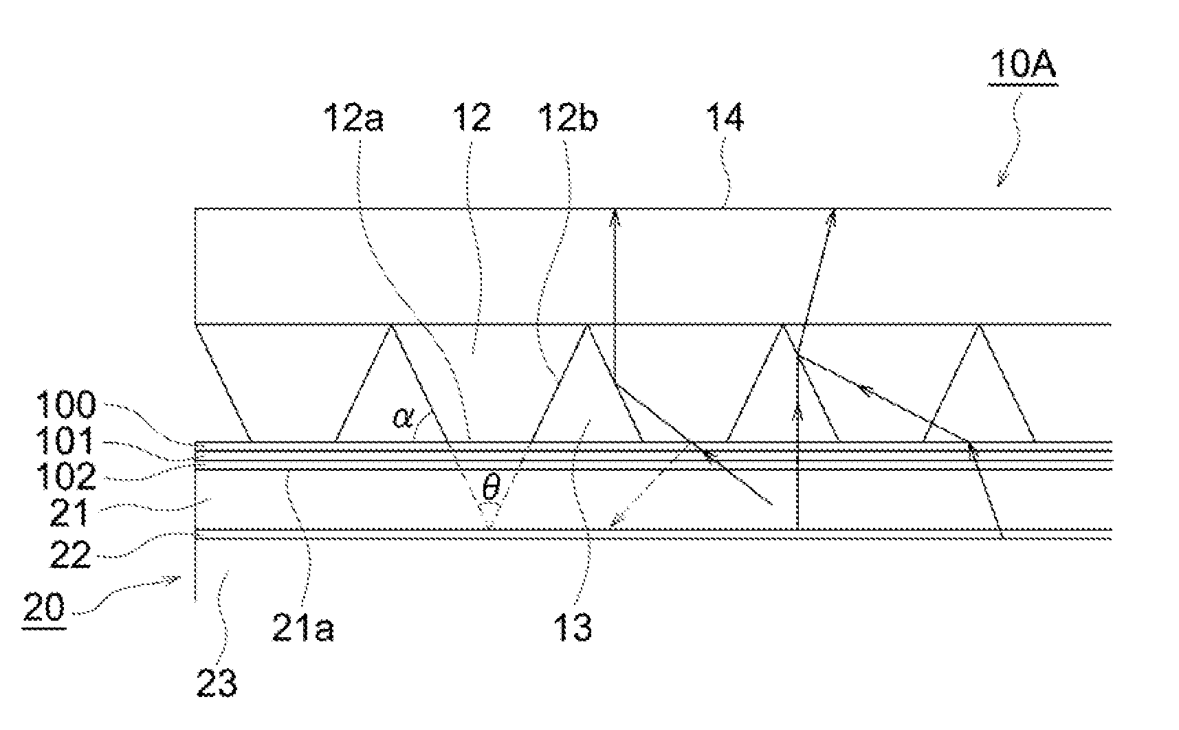
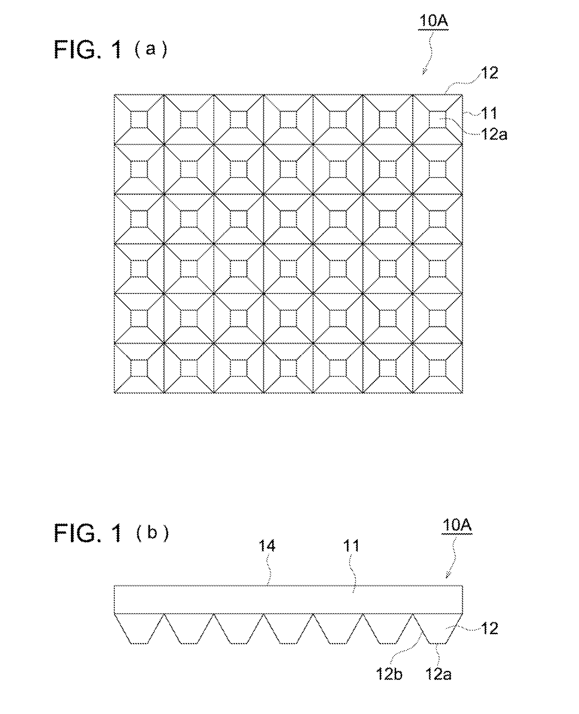
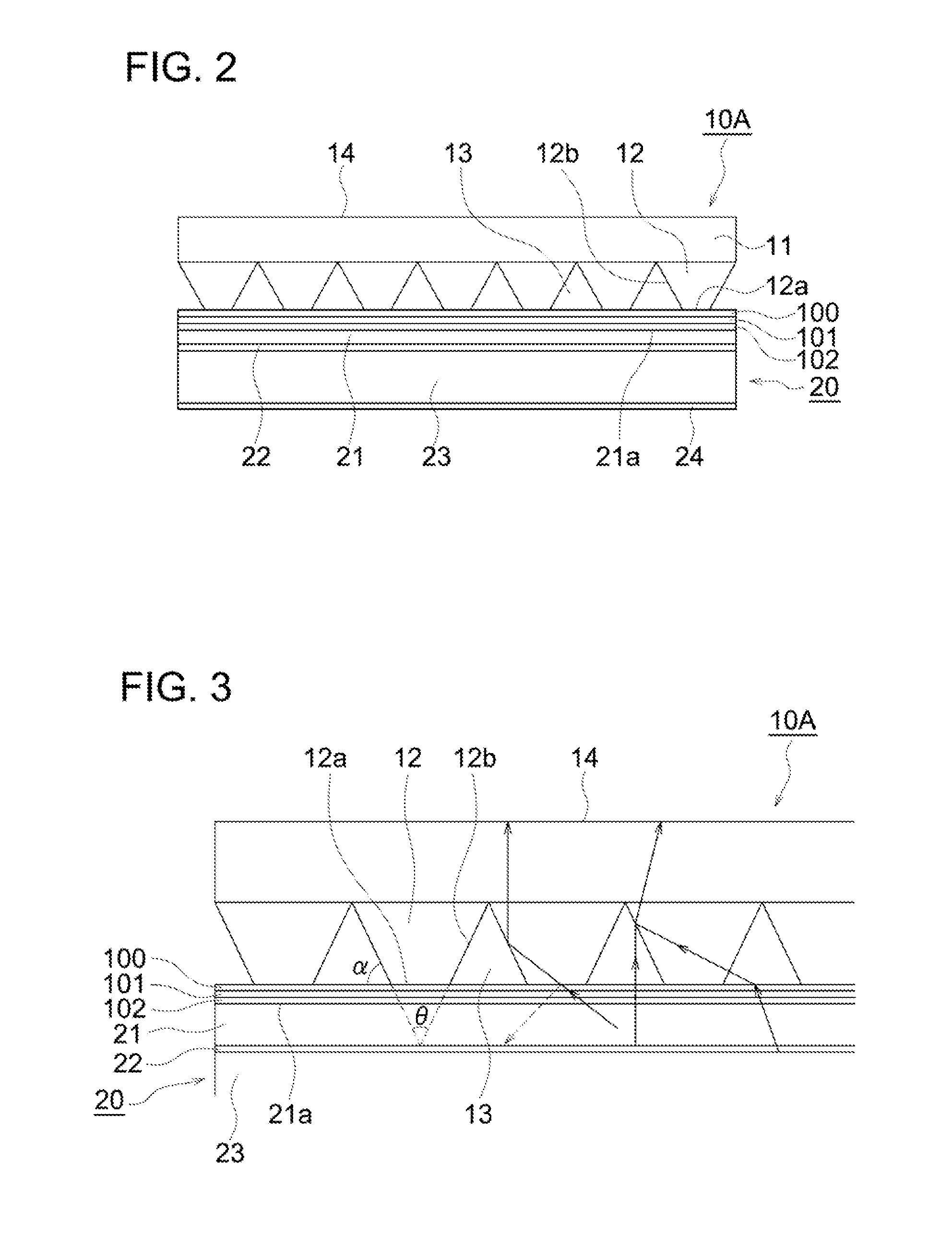
[0059]In Embodiment 1, as a light regulating sheet, as shown in FIGS. 1(a) and (b), a prism array sheet 10A composed of protrusions 12 in the truncated quadrangular pyramid shape having a contracted end side which are continuously formed lengthwise and crosswise on one side of a light transmissive substrate 11 is used. Further, in this specification, contraction of the end side of the protrusions 12 means that the protrusions 12 become gradually smaller as they go away from the prism array sheet 10A and in the examples shown in FIG. 1(b) and FIGS. 2 to 8 which will be described later, is tapered off.

[0060]And, in the surface luminous body of Embodiment 1, as shown in FIG. 2, a surface luminous element 20 composed of an organic EL element in which on the surface of a transparent substrate 21 having an installed transparent electrode 22, an organic EL layer 23 and an opposite electrode 24 are installed is used. Onto a light outgoing surface 21a of the transparent substrate 21 from whi...

embodiment 2

[0074]In Embodiment 2, as shown in FIG. 7, on the light outgoing surface 21a of the surface luminous element 20, the adhesion layer composed of the transparent curable adhesion layer 103 as curable adhesion layer C, transparent resin sheet 101 and transparent pressure-sensitive adhesion layer 100 as pressure-sensitive adhesion layer D and the prism array sheet 10A are laminated in this order and the end faces 12a of the protrusions 12 of the prism array sheet 10A, pressure-sensitive adhesion layer 100, curable adhesion layer 103, and light outgoing surface 21a of the surface luminous element 20 are structured so as to be adhered optically closely.

[0075]As shown in FIG. 8, the neighborhood of the end faces 12a of the protrusions 12 of the prism array sheet 10A is formed so as to be embedded in the adhesion layer composed of the pressure-sensitive adhesion layer 100, the resin sheet 101 and curable adhesion layer 103. The adhesion layer composed of the pressure-sensitive adhesion laye...

example 1

[0150]In Example 1, similarly to the surface luminous body of Embodiment 1, the surface luminous body was formed by adhering the prism array sheet 10A to the surface luminous element 20 using the adhesion layer composed of the first pressure-sensitive adhesion layer A, resin sheet, and second pressure-sensitive adhesion layer B.

[0151]As the surface luminous element 20, as mentioned above, the surface luminous element 20 composed of the organic EL element in which the organic EL layer 23 and opposite electrode 24 were installed on the surface of the transparent substrate 21 having the installed transparent electrode 22 was used.

[0152]Here, in the surface luminous element 20, as the transparent substrate 21, non-alkali glass with dimensions of 0.7 mm (thickness)×40 mm (length)×52 mm (width) was used, and on one side of the transparent substrate 21, as the transparent electrode 22, ITO (indium oxide with tin doped) was coated on it as a film with a thickness of 150 nm, and it was patte...


PUM


Abstract

A surface luminous body including at least a surface luminous element arid a light regulating sheet, wherein the light regulating sheet includes a plurality of projections on at least one side, the ends of the projections are each in contact with the light outgoing surface of the surface light-emitting element via an adhesion layer, and a portion of the end of the projection is embedded in the adhesion layer, and wherein the adhesion layer includes a first pressure-sensitive adhesion layer A in contact with the surface luminous element, at least one resin layer, and a second pressure-sensitive adhesion layer B in contact with the light regulating sheet and a prism embedding load Fa of a pressure-sensitive adhesive used for the pressure-sensitive adhesion layer A, and a prism embedding load Fb of a pressure-sensitive adhesive used for the pressure-sensitive adhesion layer B are in a relationship of Fb / Fa≠1.

Description

[0001]This application is based on Japanese Patent Application No. 2007-014797 filed on Jan. 25, 2007 in Japanese Patent Office, the entire content of which is hereby incorporated by reference.BACKGROUND OF THE INVENTION[0002]The present invention relates to a surface luminous body and a display device and an illuminating device using it.[0003]In recent years, in correspondence with diversification of information equipment, there is an increasing need for a surface luminous element requiring little consumption power and of a small size and as one of such surface luminous elements, an electroluminescence element (hereinafter, abbreviated to an EL element) is noticed.[0004]And, such an EL element is broadly divided into an inorganic EL element and an organic EL element depending to the material used.[0005]Here, the inorganic EL element is generally structured so as to make a high electric field, act on the luminous section, accelerate electrons in the high electric field to collide wi...

Claims


Application Information

Patent Timeline
IPC IPC(8): H01J63/04
CPCG02F2001/133607G02B5/045G02F1/133607
Inventor KONDO, TOSHIYAKUISEKO, MANAMISATO, AKIRA
Owner KONICA MINOLTA INC
Learn More