Eureka AIR delivers breakthrough ideas for toughest innovation challenges, trusted by R&D personnel around the world.

Document Shredder Device

a shredder and document technology, applied in the field of document shredders, can solve the problems of limited use as recycled paper, inability to make large speed ratio between the rotating blades, and upsizing the apparatus, so as to reduce the overall apparatus, reduce the speed ratio, and restrict the effect of paper transpor

Inactive Publication Date: 2008-07-31
KURAOKA TOSHIAKI
View PDF18 Cites 22 Cited by
  • Summary
  • Abstract
  • Description
  • Claims
  • Application Information

AI Technical Summary

Benefits of technology

[0022]The shredder according to an aspect of the present invention is small in size, because the transport system that holds and transports the paper and the shredding system are incorporated in such a manner as having a part of elements in common, and since the point of action is provided independently from the transport system, it is possible to enlarge the speed ratio between the paper transporting speed and the rotating speed of the shredding blade. Furthermore, shredding is performed while the paper up to the end is firmly held by the transport system, whereby it is possible to shred the paper entirely up to the end with reliability, by only onetime passing of the paper.PREFERRED EMBODIMENTS OF THE INVENTION
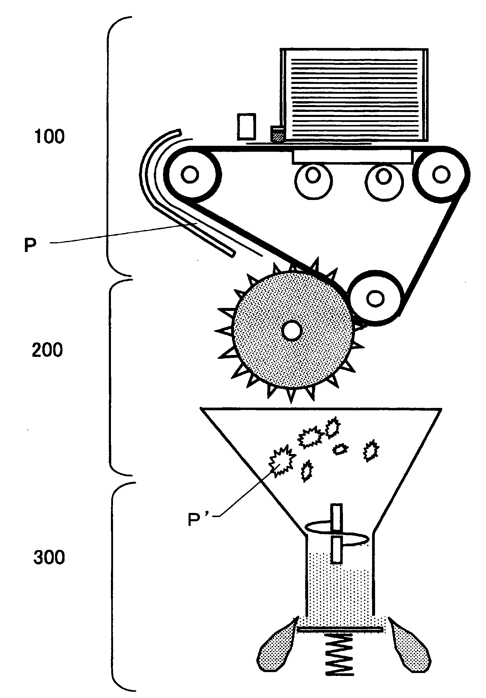
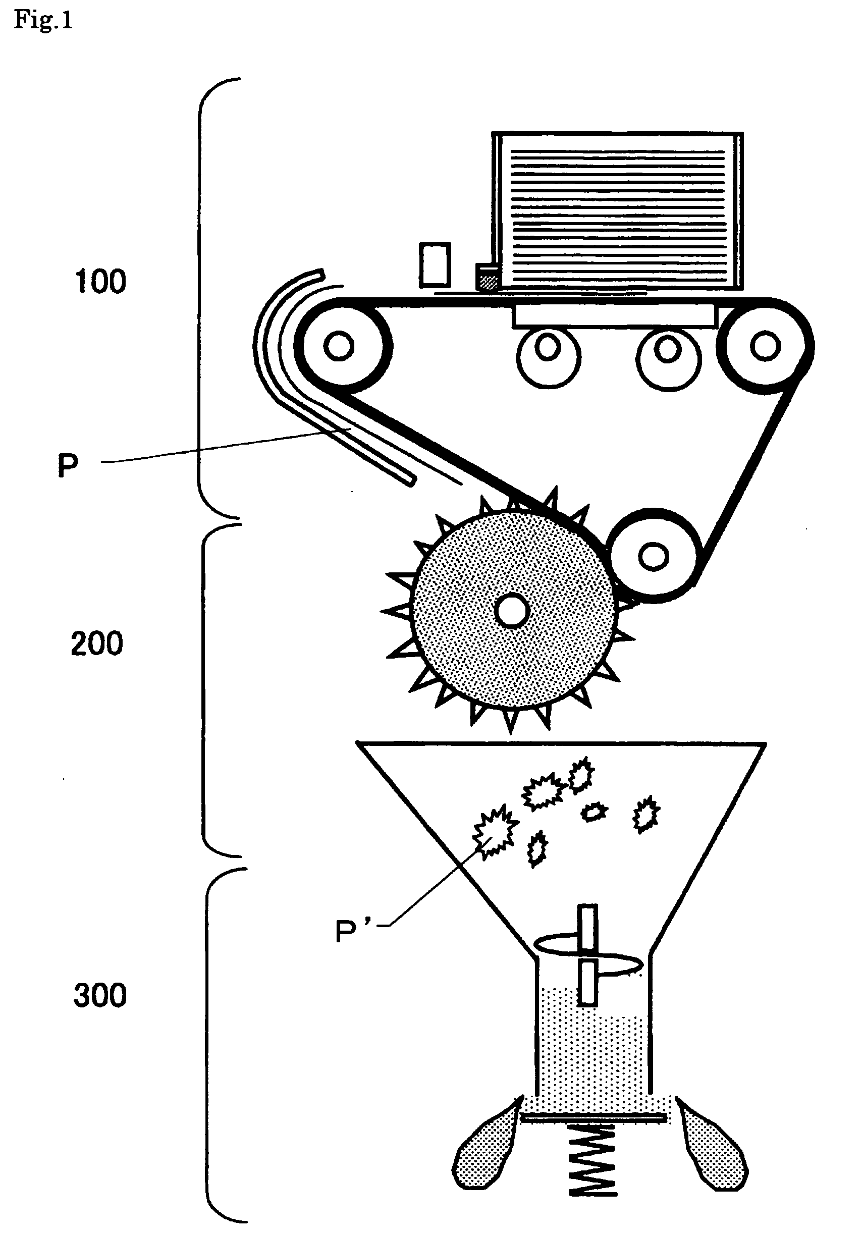
[0023]Hereinafter, exemplary embodiments of a document shredder and a shred compressor according to an aspect of the present invention will be explained. FIG. 1 illustrates an overview of the document shredder according to an aspect of the present invention, and the document shredder is provided with a paper feeder 100 that stores waste paper and separates the paper to feed an appropriate volume thereof, a shredding part 200 that subjects paper P fed from the paper feeder 100 to a shredding process, and a compression part 300 that compresses a shred P′ after shredded by the shredding part 200.
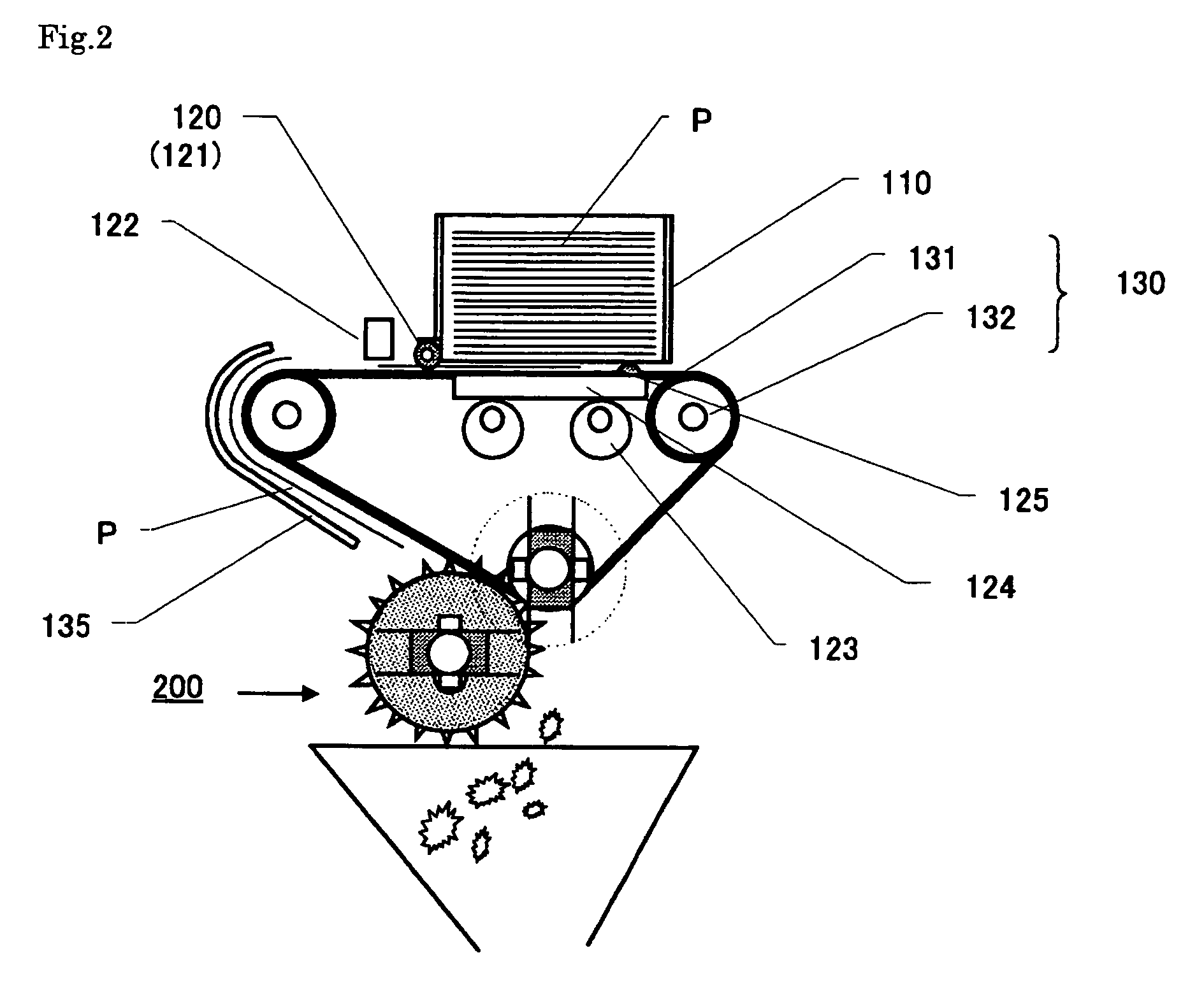
[0024]As shown FIG. 2, the paper feeder 100 is provided with a paper storage 110 that is capable of storing a large volume of paper to be discarded collectively, a paper separation mechanism 120 that takes out an appropriate number of sheets of paper P separately from the paper storage 110, and a paper transport mechanism 130 made up of a belt 131 and pulleys 132. There are two or more lines of belt 131 being provided in the width direction of the paper (in the vertical direction with respect to the plane of the figure). The paper storage 110 is formed by a box-like member to store the paper to be discarded in such a manner as being stacked therein. A part of its bottom is opened so that a sheet on the lower end of the paper being stored comes into contact with the belt 131 of the paper transport part 130. A paper ejecting side of the paper storage 110 is also provided with an opening so as to enabling ejection of the paper.
[0025]The paper transport mechanism 130 is provided with the pulleys 132 more than one, the belt 131 that is looped over these pulleys, and a paper guide 135 that guides transporting of the paper. One of the multiple pulleys is rotary-driven by a power source not illustrated. The rotation of this pulley 132 turns the belt 131 counterclockwise in the figure, and ejects the paper being in contact with the belt 131 at the lower end of the paper storage 110, to the left in the figure. It is to be noted that in the embodiment as shown in the figure, the paper transport mechanism 130 also serves as a transporting system for the shredding part 200 being a subsequent element, and the transport mechanism 130 is provided with a roller and the like, on which a shredding blade as described below is fixed. In order to downsize the overall apparatus, the example as illustrated is preferable. However, the paper transport system for the paper feeder 100 and that for the shredding part 200 may be provided independently of each other.
[0026]The paper separation mechanism 120 is provided with a separation member 121 mounted on the lower end of the paper storage 110 on the paper ejection side, a sensor 122 that detects the forefront of the paper being ejected from the paper storage 110, an eccentric cam 123 that is driven by a paper detection signal from the sensor 122, and a lifter 124 that is driven by the eccentric cam 12 to restrict the transport of the paper. The separation member 121 is made of a material having a high frictional coefficient on the surface thereof, and a space between the separation member and the belt 131 is set to become narrower toward the traveling direction of the paper, thereby restricting the number of sheets of paper that is going to come out from the paper storage 110, to one or two sheets. The separation member 121 is made of a rubber roller incorporating a one-way clutch, for example, and it is rotatable about a given shaft. This rotation may be locked in the transporting direction of the paper, but freely rotatable in the reverse direction, thereby facilitating a takeout of paper at the time of jamming.
[0027]The lifter 124 is provided at a position being opposed to the bottom of the paper storage 110, placing the belt 131 therebetween, and the lifter moves up and down every rotation of the eccentric cam 123. The lifter 124 and the belt 131 are positioned in such a manner as being displaced from each other in the width direction of the paper (the vertical direction with respect to the plane of the figure), so that the vertical movement of the lifter 124 does not interfere with the belt 131. In addition, one end of the lifter 124 on the surface being in contact with the paper is provided with a projection 125 that is made of a material having a high frictional coefficient. When the sensor 122 detects the forefront of the paper and the eccentric cam 123 is rotated, the lifter 124 goes up, and firstly the projection 125 comes into contact with the lower end of the paper having not been ejected and remaining there, thereby stopping the transport thereof. When the lifter 124 goes up further, the lifter 124 lifts the whole paper and breaks off contact between the belt 131 and the paper, thereby stopping the transport of the remaining paper.

Problems solved by technology

However, since fibers in the pieces of paper being cut out by those cutting blades are broken away, the usage as recycled paper is limited.
However, if the diameters of the rotating blades are configured to be large, a speed ratio between the pair of the rotating blades cannot be made large.
Enlarging the diameters of the rotating blades and setting up a mechanism to once again shred the paper already subjected to shredding process, may cause upsizing of the apparatus.
Furthermore, a material which has a high abrasion resistance is required as a shredding blade in the conventional document shredder, causing a problem that this requirement becomes a burdensome in maintenance wise, in order to keep a high processing ability.
Therefore, there is a problem that the pieces of paper tend to jamming.
This problem of jamming may be improved to a certain extent by providing elasticity to the wall surface, but it cannot be a drastic resolution.
However, in order to change the degree of compression in the structure of the compressor as described in the Patent document 2, modification of the elasticity of the wall surface is necessary, and accordingly there is a problem that it is not easy to change the compression degree.

Method used


Image

  • Document Shredder Device
  • Document Shredder Device
  • Document Shredder Device

Examples


first example

[0038]FIG. 6 and FIG. 7 each illustrate a first exemplary embodiment of the shredding part that utilizes the belt transport system and pulleys. This shredding part 200 is provided with a transport system 230 made up of pulleys and belts, a mechanism that shreds paper, and a hopper 240 in which the paper after shredded are ejected. The mechanism that shreds the paper is connected to a driving force not illustrated, and provided with a first shaft 210 and a second shaft 220 that respectively rotate in opposite directions, plate-like shredding blade 211 being fixed on the first shaft 210, and plate-like shredding a blade 221 that is fixed on the second shaft 220 and shred (tear) the paper in cooperation with the shredding blade 211.

[0039]The paper transport system of the paper feeder 100 described above may also serve as the transport system 230. In the exemplary embodiment as illustrated, the transport system 230 is made up of three pulleys 232a, 232b, and 232c, the belt 231 that is l...

second example

[0053]Exemplary embodiments of the shredding part that utilizes a gear will be explained. FIGS. 11, 12, 13 and 14 illustrate the fourth exemplary embodiment and its modifications utilizing multiple gears. The shredding part according to the present exemplary embodiment simplifies a power source by using multiple groups of gears, and a point of action of the shredding system is moved a little backward with respect to the paper transport system. Accordingly, a shredding tensile force applied to the paper is stabilized and shredding the paper up to the end thereof can be performed with reliability. By using gears for the paper transport system, the paper proceeding to the shredding system is wrinkled in advance. Therefore, the shredding blade easily catches the paper and tearing operation is facilitated.

[0054]FIG. 11 and FIG. 12 are respectively a side view and a top view of the shredding part according to the fourth exemplary embodiment. This shredding part 500 includes a first gear-l...


PUM


Abstract

A document shredder is provided with a transport system that holds and transports paper, and a shredding system that shreds the paper while rotating at a circumferential speed higher than a transporting speed of the transport system, wherein, a part of elements constituting the transport system is in common with a part of elements constituting the shredding system and a point of action of the transport system is placed substantially at the same position as a point of action of the shredding system, with respect to a paper transporting direction, and alternatively, the shredding system is arranged successively from the transport system. Since this shredder is assembled in such a manner that a part of elements constituting the transport system to hold and transport the paper is in common with a part of elements constituting the shredding system, it is possible to be downsized. Furthermore, since the points of action are provided independently from the transport system, it is possible to enlarge the speed ratio between the paper transporting speed and the rotating speed of the shredding blade, whereby the paper entirely up to the end can be shredded with reliability, by only onetime passing of the paper.

Description

TECHNICAL FIELD[0001]The present invention relates to a document shredder that finely shreds a document to be discarded for the purpose of maintaining confidentiality, and discards the document whose contents are rendered unreadable. More particularly, the present invention relates to a document shredder that is able to supply shredded paper containing a paper fiber being kept long without being cut off, thereby allowing the shredded paper to be suitable for recycling.RELATED ART[0002]A currently dominant document shredder employs a method to cut out paper, by using round blades that are rotated in such a manner as being opposed to and in contact with one another. However, since fibers in the pieces of paper being cut out by those cutting blades are broken away, the usage as recycled paper is limited. In order to address this problem, there is developed an apparatus that considers usage of paper after the cutoff, and shreds paper by tearing, not by cutting off. For example, Patent d...

Claims


Application Information

Patent Timeline
Patent Type & Authority Applications(United States)
IPC IPC(8): B02C18/06
CPCB02C18/0007B02C18/2216B02C18/2241B02C18/225B30B9/3089B02C18/2291B02C2018/003B02C2018/0061B02C18/2283B02C18/18B02C18/22B02C18/24B02C4/02
Inventor KURAOKA, TOSHIAKI
Owner KURAOKA TOSHIAKI
Why Eureka
Eureka Blog
Learn More