Drive system for a motor vehicle

a technology for motor vehicles and drive systems, applied in the direction of clutches, fluid couplings, yielding couplings, etc., can solve the problems of increasing assembly work, needing expensive special tools, etc., and achieve the effect of simple design and easy installation

Inactive Publication Date: 2008-07-31
ZF FRIEDRICHSHAFEN AG
View PDF4 Cites 5 Cited by
  • Summary
  • Abstract
  • Description
  • Claims
  • Application Information

AI Technical Summary

Benefits of technology

[0006]An object of the present invention is to provide a drive system for a motor vehicle which is of simple design and easy to install but which also ensures that the various assemblies involved in the transmission of torque are reliably connected and positioned with respect to each other.
[0008]In the inventive drive system, a clear separation is made between the function of establishing the torque-transmitting connection and the function of axially positioning or axially supporting the torque-transmitting assembly. This means that the axial plug-in connection arrangement does not have to be designed in such a way that it also, simultaneously, ensures the axial positioning or axial support of the torque-transmitting assembly. This allows, for example, the possibility of designing the axial plug-in connection arrangement with a comparatively high degree of elasticity or flexibility, so that it can compensate for or allow axial offsets or wobbling movements. The torque-transmitting assembly is held in a defined position by the position of the gearbox and by the axial support of the torque-transmitting assembly on this gearbox.
[0010]The reliable torque-transmitting functionality of the two plug-in connection assemblies can be achieved by designing one of the assemblies, i.e., the first plug-in connection assembly or the second plug-in connection assembly, with a set of teeth on its inside circumference and the other assembly, i.e., the second plug-in connection assembly or the first plug-in connection assembly, with a set of teeth on its outside circumference. In addition, the first plug-in connection assembly and the second plug-in connection assembly can be supported radially against each other by a radial support arrangement.
[0012]As previously mentioned, it is a special advantage of the inventive design that at least one of the plug-in connection assemblies can be designed with radial elasticity without leading to the danger of impairment to the defined positioning of, for example, the torque-transmitting assembly.
[0013]The torque-transmitting assembly can be supported axially on the gearbox in the direction facing away from the drive shaft and pretensioned in the direction toward this axial support by a pretensioning arrangement. This makes it possible to use relatively simple axial support bearings, which need to absorb only compressive loads.

Problems solved by technology

The disadvantage of this type of screwed joint is that the areas in which the threaded elements used for this purpose are usually provided are comparatively difficult to reach, which increases the amount of assembly work required and often makes it necessary to use expensive special tools.

Method used


Image

  • Drive system for a motor vehicle
  • Drive system for a motor vehicle
  • Drive system for a motor vehicle

Examples


Embodiment Construction

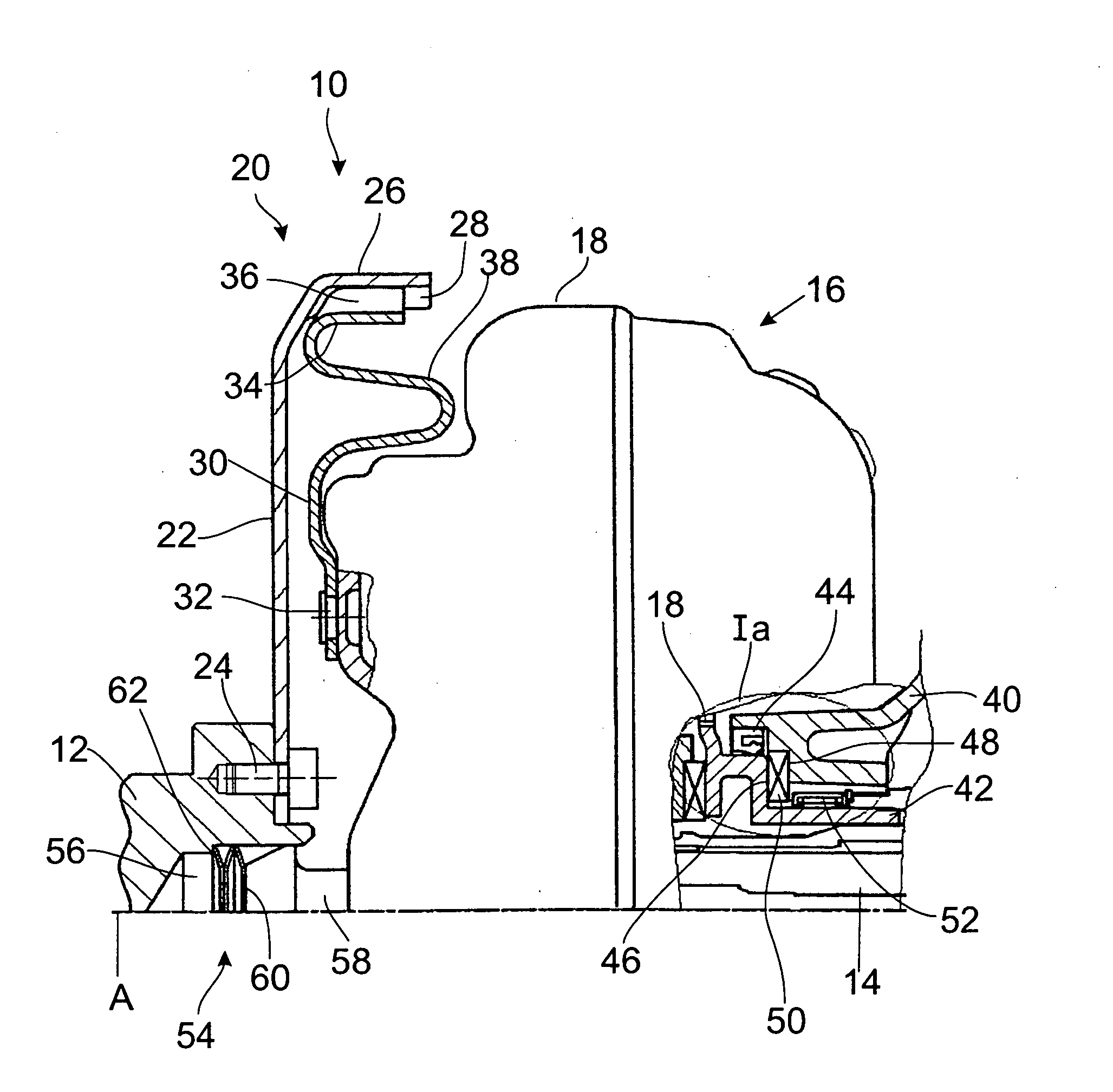
[0024]FIG. 1 shows a schematic diagram of part of a drive system 10 for a motor vehicle. This drive system 10 has as one of its essential components or assemblies a drive shaft 12 of a drive unit (not shown). This drive unit can be an internal combustion engine, in which case the drive shaft 12 can be the crankshaft. On the takeoff side, the drive system 10 has a gearbox input shaft 14 of a gearbox. The torque is transmitted between the drive shaft 12 and the gearbox input shaft 14 by a torque-transmitting assembly 16, which, in the example shown here, is designed as a hydrodynamic torque converter. On the input side, that is, by means of the converter housing 18, this torque-transmitting assembly 16 is or is to be connected for rotation in common around the axis of rotation A to the drive shaft 12 by means of an axial plug-in connection arrangement 20.

[0025]The axial plug-in connection arrangement 20 includes a first plug-in connection assembly 22, which is designed essentially in ...


PUM


Abstract

A drive system for a motor vehicle comprises a drive unit with a drive shaft and a torque-transmitting assembly, which is to be connected on the drive side to the drive shaft for rotation in common around an axis of rotation (A) and which is to be connected on the takeoff side to a gearbox. The drive-side connection is accomplished by means of an axial plug-in connection arrangement, and the torque-transmitting assembly is supported in at least one axial direction on the gearbox.

Description

BACKGROUND OF THE INVENTION[0001]1. Field of the Invention[0002]The present invention pertains to a drive system for a motor vehicle. A drive system of this type generally comprises a drive unit with a drive shaft and a torque-transmitting assembly, which is to be connected on the drive side to the drive shaft of the drive unit for rotation in common around an axis of rotation and connected on the takeoff side to a gearbox.[0003]2. Description of the Related Art[0004]It is known that, in the drive trains of motor vehicles, the drive shaft of a drive unit such as the crankshaft of an internal combustion engine can be connected to a torque-transmitting assembly such as a hydrodynamic torque converter or a friction clutch by the use of a screwed joint. So-called flex plates, for example, can be used for this purpose. The radially inner area of the plate is usually screwed to the drive shaft, whereas the radially outer area of the plate is connected to the torque-transmitting assembly, ...

Claims


Application Information

Patent Timeline
IPC IPC(8): F16D33/00
CPCF16D3/77F16D1/101
Inventor FREY, PETERKUHNER, MICHAELMARKOW, ALEXANDERHEULER, MICHAELGRUMBACH, MARTINSICH, BERNHARDREISER, ROBERTHAMMER, PETER
Owner ZF FRIEDRICHSHAFEN AG
Why Eureka
Try Eureka